Installation
INSTALLATION
PROCEDURE
1. ALIGN FRONT WHEELS STRAIGHT AHEAD
2. INSTALL STEERING COLUMN ASSEMBLY
NOTICE:
Make sure that the wire harness does not contact the steering column assembly.
(a) Install the steering column assembly using the bolt and 2 nuts.
Torque:
36 N·m {367 kgf·cm, 27 ft·lbf}
(b) Connect each connector and engage each clamp on the steering column assembly.
(c) Engage the wire harness clamp of the power steering ECU.
(d) Connect the 2 connectors of the power steering ECU.
3. CONNECT NO. 2 STEERING INTERMEDIATE SHAFT ASSEMBLY
(a) Align the alignment marks of the No. 2 steering intermediate shaft assembly and the steering column assembly. |
|
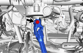
(b) Connect the No. 2 steering intermediate shaft assembly to the steering column assembly.
(c) Install the bolt.
Torque:
64 N·m {653 kgf·cm, 47 ft·lbf}
4. INSTALL NO. 2 STEERING INTERMEDIATE SHAFT ASSEMBLY
(a) Align the alignment marks of the No. 2 steering intermediate shaft assembly and the steering gear assembly. |
|
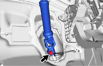
(b) Install the No. 2 steering intermediate shaft assembly onto the steering gear assembly.
(c) Install the bolt.
Torque:
64 N·m {653 kgf·cm, 47 ft·lbf}
5. INSTALL COLUMN HOLE COVER SOUND INSULATION SHEET
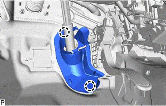
(a) Engage the 2 claws to install the column hole cover sound insulation sheet. |
 |
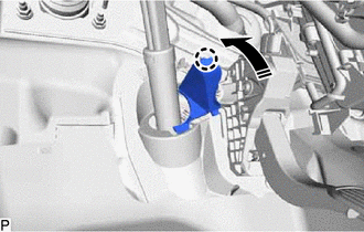
(b) Engage the claw to close the column hole cover sound insulation sheet.
 |
Engage in this direction |
6. INSTALL STOP LIGHT SWITCH ASSEMBLY
Click here
7. INSTALL NO. 1 AIR DUCT
(a) Engage the 3 claws to install the new No. 1 air duct.
(b) Install the 2 bolts.
8. INSTALL CONSOLE BOX INSERT
Click here
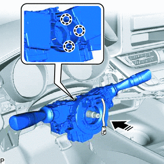
9. INSTALL COMBINATION SWITCH ASSEMBLY WITH SPIRAL CABLE SUB-ASSEMBLY
NOTICE:
- Do not replace the spiral cable sub-assembly with sensor while the battery is connected and the ignition switch is in the ON position.
- Do not swap the spiral cable sub-assembly with sensor without the steering wheel installed while the battery is connected and the ignition switch is in the ON position.
- Make sure the steering wheel assembly is installed and in the straight-ahead position when checking the steering angle sensor.
(a) Engage the 3 claws to install the combination switch assembly with spiral cable sub-assembly onto the steering column assembly, as shown in the illustration.
|
Install in this direction |
(b) Connect each connector to the combination switch assembly and the spiral cable sub-assembly.
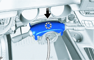
10. INSTALL STEERING COLUMN UPPER COVER
(a) Engage the 2 claws and 4 clips to connect the steering column upper cover.
|
Install in this direction |
(b) Engage the claw to install the steering column upper cover, as shown in the illustration.
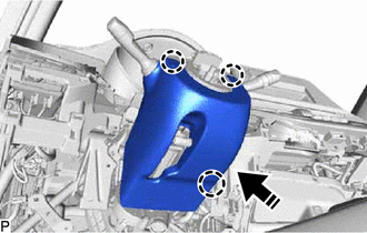
11. INSTALL STEERING COLUMN LOWER COVER SUB-ASSEMBLY
NOTICE:
If the steering column lower cover sub-assembly is installed in the wrong order, the parts may break.
|
Install in this direction |
(a) Engage the 3 claws to install the steering column lower cover sub-assembly, as shown in the illustration.
(b) Engage the 4 claws.
(c) Install the 2 screws.
12. INSTALL NO. 1 INSTRUMENT PANEL LOWER AIRBAG ASSEMBLY
Click here
13. ALIGN FRONT WHEELS STRAIGHT AHEAD
14. INSPECT AND ADJUST SPIRAL CABLE SUB-ASSEMBLY WITH SENSOR
Click here
15. INSTALL STEERING WHEEL ASSEMBLY
Click here
16. INSPECT STEERING WHEEL CENTERING
17. INSTALL HORN BUTTON ASSEMBLY
Click here
18. CALIBRATE TORQUE SENSOR ZERO POINT
Click here