Front RH seat heater does not operate
DESCRIPTION
When the seat heater switch on the air conditioning control assembly is operated, the right seat heater control sub-assembly receives the signal. The right seat heater control sub-assembly receives the signal and operates the front seat heater.
WIRING DIAGRAM
TMC manufactured
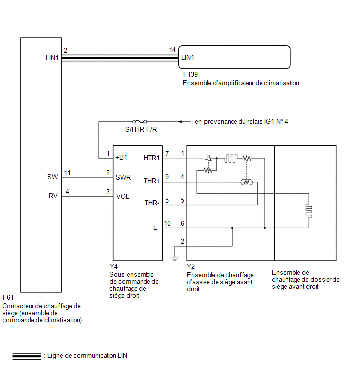
TMMT manufactured
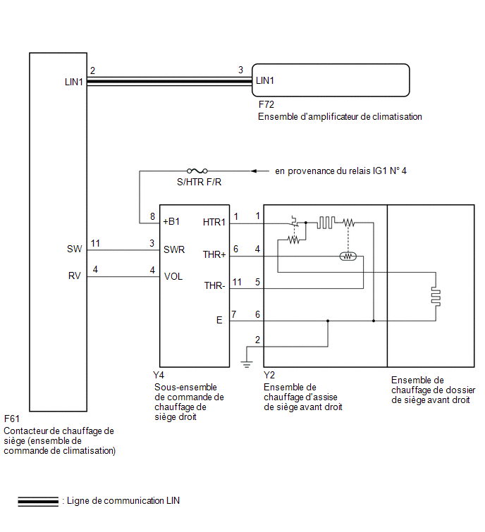
PRECAUTION / NOTICE / HINT
NOTICE:
- If the battery voltage is low, the seat heater system may not operate. Refer to the Data List for the seat heater system.
Click here

- Check the fuses for the circuits related to this system before performing the following procedure.
PROCEDURE
CLEAR DTCs
(a) Clear the DTCs.
Click here
|

CHECK WHETHER DTCs ARE OUTPUT
(a) Check the DTCs.
Click here
OK:
DTC B14B5 is not output.
Result:
Result | Proceed to |
|---|---|
OK (Manufactured by TMC) |
A |
OK (Manufactured by TMMT) |
B |
NG |
C |
| B |  |
GO TO STEP 12 |
| C | |
GO TO DIAGNOSTIC TROUBLE CODE CHART |
|
INSPECT WIRE HARNESS AND CONNECTOR (IG POWER SOURCE - RIGHT SEAT HEATER CONTROL SUB-ASSEMBLY)
(a) Disconnect the right seat heater control sub-assembly connector. |
|
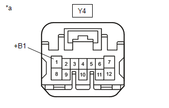
(b) Measure the voltage according to the value(s) in the table below.
Standard voltage:
Tester Connection | Ignition switch position | Specified Condition |
|---|---|---|
Y4-1 (+B1) - Body ground |
Ignition Switch in ON position |
11 à 14 V |
Ignition Switch in OFF position |
Below 1 V |
| NG | |
REPAIR OR REPLACE HARNESS OR CONNECTOR |
|
INSPECT WIRE HARNESS AND CONNECTOR (RIGHT SEAT HEATER CONTROL SUB-ASSEMBLY - RIGHT FRONT SEAT HEATER CUSHION ASSEMBLY - BODY GROUND)
(a) Disconnect the Y4 right seat heater control sub-assembly connector.
(b) Disconnect the Y2 right front seat heater cushion assembly connector.
(c) Measure the resistance according to the value(s) in the table below.
Standard resistance:
Tester Connection | Condition | Specified Condition |
|---|---|---|
Y4-7 (HTR1) - Y2-1 |
Always |
Below 1 Ω |
Y4-9 (THR+) - Y2-4 |
Always |
Below 1 Ω |
Y4-5 (THR-) - Y2-5 |
Always |
Below 1 Ω |
Y4-10 (E) - Y2-6 |
Always |
Below 1 Ω |
Y2-2 - Body ground |
Always |
Below 1 Ω |
Y4-7 (HTR1) or Y2-1 - Body ground |
Always |
10 kΩ minimum |
Y4-9 (THR+) or Y2-4 - Body ground |
Always |
10 kΩ minimum |
Y4-5 (THR-) or Y2-5 - Body ground |
Always |
10 kΩ minimum |
Y4-10 (E) or Y2-6 - Body ground |
Always |
10 kΩ minimum |
| NG | |
REPAIR OR REPLACE HARNESS OR CONNECTOR |
|
INSPECT RIGHT FRONT SEAT HEATER CUSHION ASSEMBLY
(a) Remove the right front seat heater cushion assembly.
Click here
(b) Inspect the right front seat heater cushion assembly.
Click here
| NG | |
REPLACE RIGHT FRONT SEAT HEATER CUSHION ASSEMBLY |
|
INSPECT RIGHT FRONT SEAT HEATER BACK ASSEMBLY
(a) Remove the right front seat heater back assembly.
Click here
(b) Inspect the right front seat heater back assembly.
Click here
| NG | |
REPLACE RIGHT FRONT SEAT HEATER BACK ASSEMBLY |
|
INSPECT WIRE HARNESS AND CONNECTOR (SEAT HEATER SWITCH (AIR CONDITIONING CONTROL ASSEMBLY) - RIGHT SEAT HEATER CONTROL SUB-ASSEMBLY)
(a) Disconnect the F61 seat heater switch (air conditioning control assembly) connector.
(b) Disconnect the Y4 right seat heater control sub-assembly connector.
(c) Measure the resistance according to the value(s) in the table below.
Standard resistance:
Tester Connection | Condition | Specified Condition |
|---|---|---|
F61-11 (SW) - Y4-2 (SWR) |
Always |
Below 1 Ω |
F61-4 (RV) - Y4-3 (VOL) |
Always |
Below 1 Ω |
F61-11 (SW) or Y4-2 (SWR) - Body ground |
Always |
10 kΩ minimum |
F61-4 (RV) or Y4-3 (VOL) - Body ground |
Always |
10 kΩ minimum |
| NG | |
REPAIR OR REPLACE HARNESS OR CONNECTOR |
|
REPLACE RIGHT SEAT HEATER CONTROL SUB-ASSEMBLY
(a) Temporarily replace the right seat heater control sub-assembly with a new or normally functioning one.
Click here
|
CHECK OPERATION OF SEAT HEATER SYSTEM
(a) Confirm that the seat heater system operates normally.
OK:
The seat heater system operates normally.
| OK | |
END (THE SEAT HEATER CONTROL SUB-ASSEMBLY WAS FAULTY) |
|
REPLACE SEAT HEATER SWITCH (AIR CONDITIONING CONTROL ASSEMBLY)
(a) Temporarily replace the seat heater switch (air conditioning control assembly) with a new or normally functioning one.
Click here
|
CHECK OPERATION OF SEAT HEATER SYSTEM
(a) Confirm that the seat heater system operates normally.
OK:
The seat heater system operates normally.
| OK | |
END (THE SEAT HEATER SWITCH (AIR CONDITIONING CONTROL ASSEMBLY) WAS FAULTY) |
| NG | |
REPLACE AIR CONDITIONING AMPLIFIER ASSEMBLY |
INSPECT WIRE HARNESS AND CONNECTOR (IG POWER SOURCE - RIGHT SEAT HEATER CONTROL SUB-ASSEMBLY)
(a) Disconnect the right seat heater control sub-assembly connector. |
|
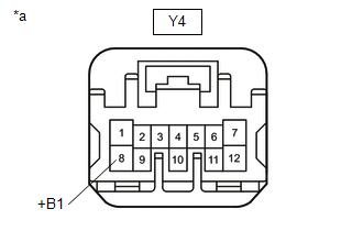
(b) Measure the voltage according to the value(s) in the table below.
Standard voltage:
Tester Connection | Ignition switch position | Specified Condition |
|---|---|---|
Y4-8 (+B1) - Body ground |
Ignition Switch in ON position |
11 à 14 V |
Ignition Switch in OFF position |
Below 1 V |
| NG | |
REPAIR OR REPLACE HARNESS OR CONNECTOR |
|
INSPECT WIRE HARNESS AND CONNECTOR (RIGHT SEAT HEATER CONTROL SUB-ASSEMBLY - RIGHT FRONT SEAT HEATER CUSHION ASSEMBLY - BODY GROUND)
(a) Disconnect the Y4 right seat heater control sub-assembly connector.
(b) Disconnect the Y2 right front seat heater cushion assembly connector.
(c) Measure the resistance according to the value(s) in the table below.
Standard resistance:
Tester Connection | Condition | Specified Condition |
|---|---|---|
Y4-1 (HTR1) - Y2-1 |
Always |
Below 1 Ω |
Y4-6 (THR+) - Y2-4 |
Always |
Below 1 Ω |
Y4-11 (THR-) - Y2-5 |
Always |
Below 1 Ω |
Y4-7 (E) - Y2-6 |
Always |
Below 1 Ω |
Y2-2 - Body ground |
Always |
Below 1 Ω |
Y4-1 (HTR1) or Y2-1 - Body ground |
Always |
10 kΩ minimum |
Y4-6 (THR+) or Y2-4 - Body ground |
Always |
10 kΩ minimum |
Y4-11 (THR-) or Y2-5 - Body ground |
Always |
10 kΩ minimum |
Y4-7 (E) or Y2-6 - Body ground |
Always |
10 kΩ minimum |
| NG | |
REPAIR OR REPLACE HARNESS OR CONNECTOR |
|
INSPECT RIGHT FRONT SEAT HEATER CUSHION ASSEMBLY
(a) Remove the right front seat heater cushion assembly.
Click here
(b) Inspect the right front seat heater cushion assembly.
Click here
| NG | |
REPLACE RIGHT FRONT SEAT HEATER CUSHION ASSEMBLY |
|
INSPECT RIGHT FRONT SEAT HEATER BACK ASSEMBLY
(a) Remove the right front seat heater back assembly.
Click here
(b) Inspect the right front seat heater back assembly.
Click here
| NG | |
REPLACE RIGHT FRONT SEAT HEATER BACK ASSEMBLY |
|
INSPECT WIRE HARNESS AND CONNECTOR (SEAT HEATER SWITCH (AIR CONDITIONING CONTROL ASSEMBLY) - RIGHT SEAT HEATER CONTROL SUB-ASSEMBLY)
(a) Disconnect the F61 seat heater switch (air conditioning control assembly) connector.
(b) Disconnect the Y4 right seat heater control sub-assembly connector.
(c) Measure the resistance according to the value(s) in the table below.
Standard resistance:
Tester Connection | Condition | Specified Condition |
|---|---|---|
F61-11 (SW) - Y4-3 (SWR) |
Always |
Below 1 Ω |
F61-4 (RV) - Y4-4 (VOL) |
Always |
Below 1 Ω |
F61-11 (SW) or Y4-3 (SWR) - Body ground |
Always |
10 kΩ minimum |
F61-4 (RV) or Y4-4 (VOL) - Body ground |
Always |
10 kΩ minimum |
| NG | |
REPAIR OR REPLACE HARNESS OR CONNECTOR |
|
REPLACE RIGHT SEAT HEATER CONTROL SUB-ASSEMBLY
(a) Temporarily replace the right seat heater control sub-assembly with a new or normally functioning one.
Click here
|
CHECK OPERATION OF SEAT HEATER SYSTEM
(a) Confirm that the seat heater system operates normally.
OK:
The seat heater system operates normally.
| OK | |
END (THE SEAT HEATER CONTROL SUB-ASSEMBLY WAS FAULTY) |
|
REPLACE SEAT HEATER SWITCH (AIR CONDITIONING CONTROL ASSEMBLY)
(a) Temporarily replace the seat heater switch (air conditioning control assembly) with a new or normally functioning one.
Click here
|
CHECK OPERATION OF SEAT HEATER SYSTEM
(a) Confirm that the seat heater system operates normally.
OK:
The seat heater system operates normally.
| OK | |
END (THE SEAT HEATER SWITCH (AIR CONDITIONING CONTROL ASSEMBLY) WAS FAULTY) |
| NG | |
REPLACE AIR CONDITIONING AMPLIFIER ASSEMBLY |