Installation
INSTALLATION
PRECAUTION / NOTICE / HINT
HINT:
- Repeat the same procedure for the right side and the left side.
- The following procedure applies to the left side.
PROCEDURE
1. REPAIR INSTRUCTIONS
(a) Clean the surface of the vehicle body.
(1) Using a heat light, heat the surface of the vehicle body.
Heating TemperatureItem | Temperature |
|---|---|
Vehicle Body |
40 à 60 °C |
CAUTION:
- Do not touch heated parts or the heat lamp. Touching them may cause burns.
- Prolonged contact with heated parts may cause burns.
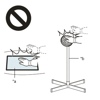
*a |
Hot Surface |
*b |
Heat Lamp |
NOTICE:
Do not overheat the vehicle body.
(2) Remove any tape residue using a cleaning solvent.
(b) Installation Temperature
(1) When the ambient temperature is below 15 °C, perform the installation procedure after heating the vehicle body surface (door frame installation surface) and the masking tape to between 20 and 30 °C using a heat lamp. When the ambient temperature is above 35 °C, cool the vehicle body surface (door frame installation surface) and the masking tape to between 20 and 30 °C before installation.
HINT:
- The optimum temperature for installing the tape is 25 °C.
- When the temperature is low, the adhesive tape hardens and falls off easily. When the temperature is high, the tape loses its elasticity.
(c) Before Installation
(1) Remove any roughness or dirt from the vehicle body paint surface where the tape will be installed (door frame installation surface). If this is not done, air will be trapped under the tape surface, resulting in an improper appearance.
HINT:
Spray water on the shop floor to prevent dust from becoming airborne.
(d) Key Points for Handling the Tape
(1) The tape bends and curls easily. Store the tape between flat pieces of cardboard or similar material, in a dry and flat location.
NOTICE:
Do not bend the tape or leave it in a location exposed to high temperatures.
(e) Key Points for Installing the Adhesive Tape (Using a Squeegee and Installation Procedure for Flat Surfaces)
NOTICE:
- Position the adhesive tape very accurately for an optimal finish and to prevent it from peeling off.
- Do not reuse the adhesive tape, as it deforms after removal.
(1) To prevent air bubbles from forming, lift the section of tape to be applied slightly so that its adhesive surface does not touch the vehicle body prematurely. Tilt the squeegee at an angle of 40 to 50° (pushing forward) or 30 to 45° (pulling) against the vehicle body surface, and press the adhesive tape onto the surface with a force of 20 to 30 N (2 to 3 kgf, 4.5 to 6.7 lbf) at a constant speed of 30 to 70 mm (1.18 to 2.76 in.) per second.
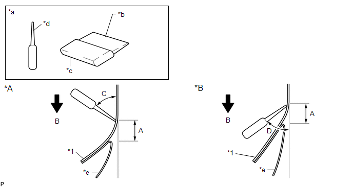
*A |
Pushing Forward |
*B |
Pulling |
*1 |
Masking Tape |
- |
- |
*a |
Side View |
*b |
Non-Padded Side |
*c |
Padded Side |
*d |
Squeegee |
*e |
Release Liner |
- |
- |
Standard measurement:
Area | Measurement | Area | Measurement |
|---|---|---|---|
A |
10 to 20 mm (0.394 to 0.787 in.) |
B |
30 to 70 mm/s (1.18 to 2.76 in./s) |
C |
40 to 50° (for pushing forward) |
D |
30 to 45° (for pulling) |
NOTICE:
Make sure to observe the specified squeegee speed, force and angle to prevent deformation or air bubble formation.
HINT:
- Either squeegee angle (pushing forward or pulling) is acceptable.
- Make sure to apply the tape while peeling the release liner 10 to 20 mm (0.394 to 0.787 in.) from the edge of the squeegee.
(f) Key Points for Installing the Tape (Using a Squeegee and Installation Procedure for Hemmed Surfaces)
(1) If the tape is difficult to apply, perform the work in several steps as shown in the illustration. Use your fingers or the padded side of a squeegee to slowly apply the tape to the vehicle flange, especially when the flange is small. HINT: When applying the tape to the back of a hemmed edge, remove the release liner and use your fingers or the padded side of a squeegee. |
|
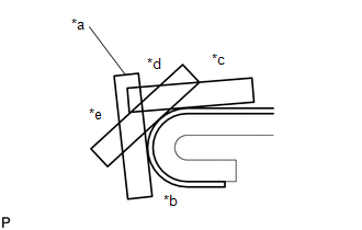
(g) Key Points for Installing the Tape (Using a Squeegee and Installation Procedure for Corner Surfaces)
(1) Remove the release liner and carefully apply the tape using your fingers.
(2) Before applying the tape to each corner surface, heat the tape using a heat lamp and apply it gradually, avoiding deformation, to achieve an optimal finish.
(h) Inspection After Installation
(1) After installation is complete, check that the tape is applied close to the surface. If the adhesive tape is not in close contact with the surface, install new adhesive tape.
NOTICE:
Do not reuse the tape.
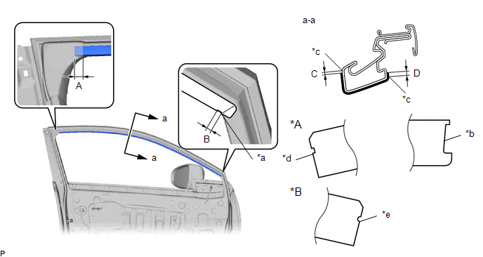
2. INSTALL NO. 2 FRONT DOOR GARNISH MOLDING
(a) Refer to the illustration to position a new No. 2 front door garnish molding.
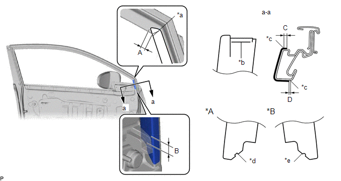
*A |
Left side |
*B |
Right side |
*a |
Point A |
*b |
Point B |
*c |
Curved Surface Edge |
*d |
Cross Section |
*e |
Round |
- |
- |
Standard measurement:
Area | Measurement | Area | Measurement |
|---|---|---|---|
A |
4.0 mm (0.157 in.) |
B |
5.0 mm (0.197 in.) |
C |
2.5 mm (0.0984 in.) |
D |
1.0 mm (0.0394 in.) |
(b) Remove the release liner and install the No. 2 front door garnish molding.
HINT:
Align point (B) on the No. 2 front door garnish molding with point (A) on the door frame, then install the No. 2 front door garnish molding.
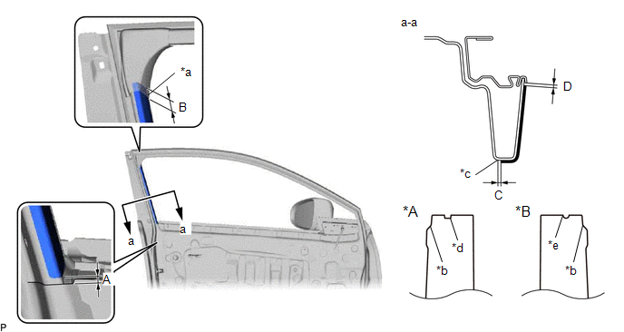
3. INSTALL FRONT DOOR OUTSIDE MOULDING
(a) Refer to the illustration to position a new front door outside moulding.
*A |
Left side |
*B |
Right side |
*a |
Point A |
*b |
Point B |
*c |
Curved Surface Edge |
*d |
Cross Section |
*e |
Round |
- |
- |
Standard measurement:
Area | Measurement | Area | Measurement |
|---|---|---|---|
A |
10.0 mm (0.394 in.) |
B |
4.0 mm (0.157 in.) |
C |
1.0 mm (0.0394 in.) |
D |
2.5 mm (0.0984 in.) |
(b) Remove the protective sheet and install the front door outside moulding.
HINT:
Align point (B) on the front door outside moulding with point (A) on the door frame, then install the front door outside moulding.
4. INSTALL FRONT DOOR GARNISH MOULDING NO. 4
(a) Refer to the illustration to position a new front door garnish moulding No. 4.
*A |
Left side |
*B |
Right side |
*a |
Point A |
*b |
Point B |
*c |
Curved Surface Edge |
*d |
Cross Section |
*e |
Round |
- |
- |
Standard measurement:
Area | Measurement | Area | Measurement |
|---|---|---|---|
A |
3 mm (0.118 in) |
B |
10.0 mm (0.394 in.) |
C |
1.0 mm (0.0394 in.) |
D |
-1.0 to 1.0 mm (-0.0394 to 0.0394 in.) |
(b) Remove the protective sheet and install the front door garnish moulding No. 4.
HINT:
Align point (B) on the front door garnish moulding No. 4 with point (A) on the door frame, then install the front door garnish moulding No. 4.
5. INSTALL FRONT DOOR FIXED GLASS
Click here
6. INSTALL FRONT DOOR LOWER FRAME SUB-ASSEMBLY
Click here
7. INSTALL FRONT DOOR GLASS RUN
Click here
8. INSTALL UPPER DOOR FRAME GARNISH
Click here
9. INSTALL FRONT DOOR WINDOW GLASS SUB-ASSEMBLY
Click here
10. INSTALL FRONT DOOR SERVICE HOLE COVER
Click here
11. INSTALL OUTER REAR VIEW MIRROR ASSEMBLY
Click here
12. INSTALL FRONT DOOR VENTILATION SEAL
Click here
13. INSTALL FRONT DOOR WINDOW INNER WEATHERSTRIP
Click here
14. INSTALL FRONT DOOR BELT SEAL
Click here
15. CONNECT FRONT DOOR WEATHERSTRIP
Click here
16. INSTALL FRONT DOOR LOWER FRAME SUPPORT GARNISH
Click here
17. INSTALL FRONT DOOR TRIM PANEL SUB-ASSEMBLY
Click here
18. INSTALL MULTIPLEX NETWORK MAIN SWITCH ASSEMBLY WITH FRONT ARMREST BASE UPPER PANEL (for driver side)
Click here
19. INSTALL POWER WINDOW SWITCH ASSEMBLY WITH FRONT ARMREST BASE UPPER PANEL (for front passenger side)
Click here
20. INSTALL FRONT DOOR INSIDE HANDLE GARNISH CLIP
Click here
21. CONNECT CABLE TO NEGATIVE BATTERY TERMINAL
Click here
NOTICE:
When the cable has been disconnected, some systems must be reset after the cable is reconnected.
Click here
22. INITIALIZE POWER WINDOW CONTROL SYSTEM
Click here
23. CHECK POWER WINDOW OPERATION
Click here