Setting the Fuel Injection System Self-Diagnostic Modes
The electronic control unit self-diagnostic system has normal and test operating modes. If a fault is detected while the engine is running and the electronic control unit is in normal mode, the warning lamp lights and a trouble code is stored in the on-board computer memory. The trouble code can be read in normal mode by counting the flashes of the warning lamp, as described below. After the fault is repaired, the lamp stops flashing, but the trouble codes remain in computer memory until they are erased. Test mode is used to identify a fault that occurs while the vehicle is being driven, and is also useful if the fault occurs under certain special conditions.
Before using any diagnostic mode, make sure the battery is fully charged, all electrical loads are switched off, and the engine is warmed up to operating temperature. The transmission must be in neutral.
To perform the check in normal mode, carry out the following steps:
· Make sure the throttle valve is closed, then switch on the ignition, but do not start the engine.
· Open the diagnostic panel cover on the left side of the engine compartment and, using a jumper or a piece of wire, connect terminals TE1 and E1 (the terminals are marked on the inside of the cover).
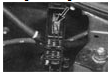
Fig. 4.4.1. Connecting terminals TE1 and E1 with a piece of wire
· Watch the warning lamp. If the system has no trouble codes stored in memory, the lamp flashes regularly at 0.26-second intervals. If trouble codes are stored, the lamp will output them one after another as two-digit numbers, with 2.5 seconds between codes and 1.5 seconds between the digits of each code.
· After recording the codes, remove the jumper wire and turn the ignition switch OFF.
To perform the test mode check, follow these steps:
· Lift the cover of the diagnostic panel on the left side of the engine compartment. Using a jumper wire or a length of wire, connect terminals TEN and E1 (the terminals are marked on the inside of the cover).
· Turn the ignition switch ON, but do not start the engine at this stage. The warning light will begin to blink.
· Now start the engine and drive the vehicle at 6 mph or faster. If possible, try to simulate the conditions under which the malfunction occurs.
· Stop the vehicle. Using a second probe or a length of wire, connect terminals TE1 and E1 of the diagnostic panel (terminals TE2 and E1 must remain connected by the first wire).
· Watch the warning light. If there are no malfunction codes in the system memory, the light will blink regularly at 0.26 second intervals. If malfunction codes are stored in memory, the light will output them one after another as two-digit numbers, with a 3.5 second interval between codes and a 1.5 second interval between digits of each code.
· To finish, remove the jumper wire and turn the ignition switch OFF.
The malfunction codes have the following meanings (Table 4.4.1):
Table 4.4.1. Malfunction Codes
| Code No. | Malfunctioning Circuit |
| 12 | Tachometer signal |
| 13 | Tachometer signal |
| 14 | Ignition signal |
| 16 | Electronic control unit control signal |
| 21 | Oxygen sensor signal. Lean mixture sensor signal |
| 22 | Engine coolant temperature sensor signal |
| 24 | Intake air temperature sensor signal |
| 25 | Lean mixture malfunction |
| 31 | Vacuum sensor signal |
| 33 | Idle speed control valve signal |
| 41 | Throttle position sensor signal |
| 42 | Vehicle speed sensor signal |
| 43 | Starter signal |
| 52 | Knock sensor signal |
| 51 | Switch condition signal |
Test yourself
A quick Toyota Carina quiz: every answer comes with an explanation and a link to the manual page.