Check open circuit
- For the open circuit in the wire harness in fig. 1, Perform a resistance check in step (b) or a voltage check in step (c) to locate the section.
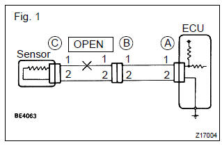
- Check the resistance.
- Disconnect connectors a and c and measure the resistance between them. Resistance: 1 Ω or less
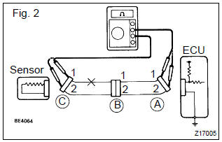
: measure the resistance while lightly shaking the wire harness vertically and horizontally.
In the case of fig. 2: Between terminal 1 of connector a and terminal 1 of connector c " 10 kΩ or higher between terminal 2 of connector a and terminal 2 of connector c " below 1 Ωtherefore, the cause is an open circuit between terminal 1 of connector a and terminal 1 of connector c.
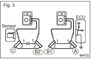
- Disconnect connector b and measure the resistance between the connectors.
In the case of fig. 3: Between terminal 1 of connector a and terminal 1 of connector b1 " below 1 w between terminal 1 of connector b2 and terminal 1 of connector c " 10 kw therefore, the cause is an open circuit between terminal 1 of connector b2 and terminal 1 of connector c.
- Check the voltage.
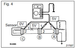
- In a circuit in which voltage is applied (to the ecu connector terminal), an open circuit can be checked by conducting a voltage check.
As shown in fig. 4, With each connector still connected, measure the voltage between the body ground and terminal 1 of connector a at the ecu 5 v output terminal, terminal 1 of connector b, and terminal 1 of connector c, in that order.
- If the results are: 5 v: between terminal 1 of connector a and body ground 5 v: between terminal 1 of connector b and body ground 0 v: between terminal 1 of connector c and body ground therefore, the cause is an open circuit in the wire harness between terminal 1 of connector b and terminal 1 of connector c.
Test yourself
A quick Toyota Corolla quiz: every answer comes with an explanation and a link to the manual page.