Compressor Lock Sensor Circuit
DTC B1422/22 Compressor Lock Sensor Circuit
SYSTEM DESCRIPTION
The ECM sends an engine speed signal to the A/C amplifier via CAN communication and BEAN communication.
The A/C amplifier reads the difference between compressor speed and engine speed. When the difference becomes too large, the A/C amplifier determines that the compressor locks, and turns the magnetic clutch off.
WIRING DIAGRAM
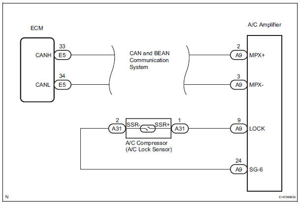
INSPECTION PROCEDURE
1 CHECK CAN COMMUNICATION SYSTEM
(a) Use the intelligent tester to check if the CAN communication system is functioning normally.
Result 


2 CHECK MULTIPLEX COMMUNICATION SYSTEM
(a) Use the intelligent tester to check if the multiplex communication system (BEAN) is functioning normally.
Result 


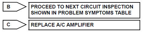
3 INSPECT A/C AMPLIFIER
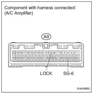
(a) Remove the A/C amplifier with the connectors still connected.
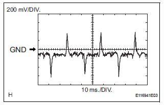
(b) Measure the waveform of the connector. 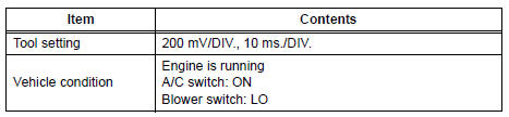
Standard 
Result 

4 INSPECT COMPRESSOR AND MAGNETIC CLUTCH (A/C LOCK SENSOR)
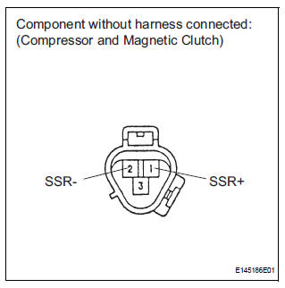
(a) Disconnect the connector from the A/C compressor.
(b) Measure the resistance according to the value(s) in the table below.
Standard resistance 


5 CHECK HARNESS AND CONNECTOR (A/C AMPLIFIER - A/C LOCK SENSOR)
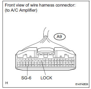
(a) Disconnect the connector from the A/C amplifier.

(b) Measure the resistance according to the value(s) in the table below.
Standard resistance 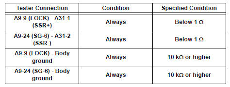


REPLACE A/C AMPLIFIER
Test yourself
A quick Toyota Sienna quiz: every answer comes with an explanation and a link to the manual page.