Atf Temperature Sensor(when Using The Engine Support Bridge)
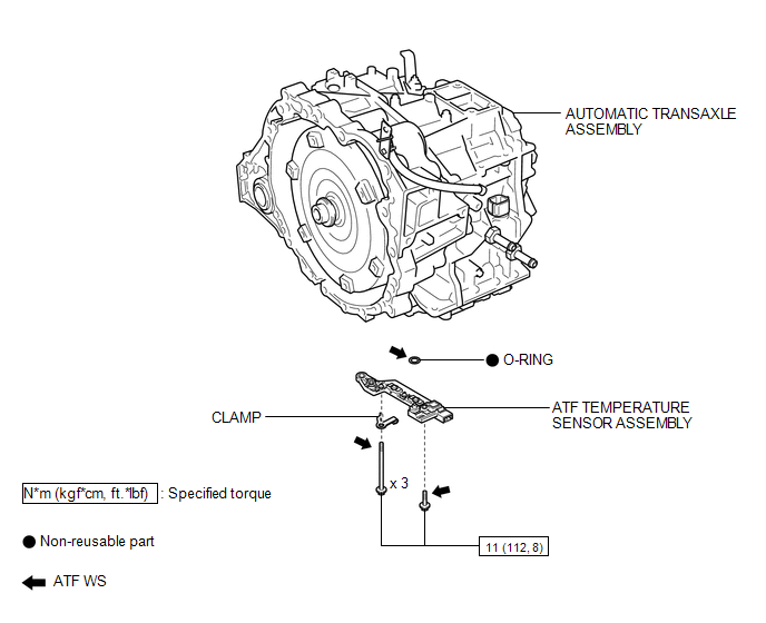
Inspection INSPECTION PROCEDURE
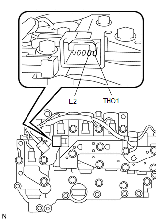
1. INSPECT ATF TEMPERATURE SENSOR ASSEMBLY
(a) Measure the resistance according to the value(s) in the table below. Standard Resistance:
If the resistance is out of the specified range with the ATF temperature shown in the preceding table, replace the ATF temperature sensor assembly. Otherwise, the driveability of the vehicle may decrease. |
 |
1. REMOVE VALVE BODY OIL STRAINER ASSEMBLY
See page 
2. REMOVE ATF TEMPERATURE SENSOR ASSEMBLY
(a) Disconnect the ATF temperature sensor assembly connector. Text in Illustration
|
 |
(b) Remove the 4 bolts, ATF temperature sensor assembly and clamp from the transmission valve body assembly.
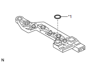
(c) Remove the O-ring from the ATF temperature sensor assembly. Text in Illustration
|
 |
1. INSTALL ATF TEMPERATURE SENSOR ASSEMBLY
(a) Coat a new O-ring with ATF and install it to the ATF temperature sensor assembly.
(b) Coat the 4 bolts with ATF.
(c) Install the ATF temperature sensor assembly and clamp to the transmission valve body assembly with the 4 bolts. Text in Illustration
Torque: 11 N·m {112 kgf·cm, 8 ft·lbf} Bolt Length: Bolt (A) 25 mm (0.984 in.) Bolt (B) 85 mm (3.35 in.) |
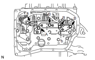 |
(d) Connect the ATF temperature sensor assembly connector.
2. INSTALL VALVE BODY OIL STRAINER ASSEMBLY
See page 
Test yourself
A quick Toyota Venza quiz: every answer comes with an explanation and a link to the manual page.