Inspection
1. INSPECT DRIVE MONITOR SWITCH
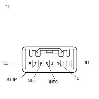
(a) Measure the resistance according to the value(s) in the table below.
Standard Resistance:
Tester Connection | Condition | Specified Condition |
|---|---|---|
3 (E) - 5 (INFO) |
INFO CLOCK*1 or INFO*2 switch is pressed |
Below 1 Ω |
3 (E) - 5 (INFO) |
INFO CLOCK*1 or INFO*2 switch is released |
10 kΩ or higher |
3 (E) - 6 (SEL) |
RESET H *1 or SELECT RESET*2 switch is pressed |
Below 1 Ω |
3 (E) - 6 (SEL) |
RESET H *1 or SELECT RESET*2 switch is released |
10 kΩ or higher |
3 (E) - 7 (STUP) |
US/M M*1 or SETUP*2 switch is pressed |
Below 1 Ω |
3 (E) - 7 (STUP) |
US/M M*1 or SETUP*2 switch is released |
10 kΩ or higher |
- *1: w/o Rear View Monitor System
- *2: w/ Rear View Monitor System
(b) Apply battery voltage from the wire harness back side between the terminals of the switch, and check the lighting condition of the drive monitor switch.
OK:
Measurement Condition | Condition | Specified Condition |
|---|---|---|
Battery negative (-) → 1 (ILL-) Battery positive (+) → 8 (ILL+) |
Always |
Drive monitor switch illuminates |
*1 |
Component without harness connected (Drive Monitor Switch) |
HINT:
If the result is not as specified, replace the drive monitor switch (See page  ).
Test yourself
A quick Toyota Venza quiz: every answer comes with an explanation and a link to the manual page.