Power Source Control ECU Malfunction (B2782)
The power management control ECU controls the power supply to activate the steering lock motor. This prevents the steering wheel from being locked while the vehicle is moving.
DTC No. | DTC Detecting Condition | Trouble Area |
|---|---|---|
B2782 |
Steering lock motor drive control circuit is defective. |
|
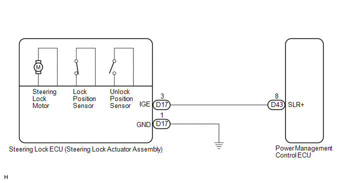
CAUTION / NOTICE / HINT
HINT:
After replacing the steering lock ECU (steering lock actuator assembly), confirm the Initialization of the steering lock (See page  ).
PROCEDURE
INSPECT STEERING LOCK ECU (STEERING LOCK ACTUATOR ASSEMBLY)
(a) Measure the voltage according to the value(s) in the table below. Standard Voltage:
HINT: The steering lock ECU and steering lock actuator assembly are supplied as a single unit. |
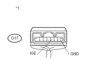 |
*1 |
Component with harness connected (Steering Lock ECU (Steering Lock Actuator Assembly)) |
| OK |  | REPLACE STEERING LOCK ECU (STEERING LOCK ACTUATOR ASSEMBLY) |
|

CHECK HARNESS AND CONNECTOR (STEERING LOCK ECU - BODY GROUND)
(a) Disconnect the D17 connector from the steering lock actuator assembly. |
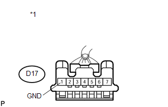 |
(b) Measure the resistance according to the value(s) in the table below.
Standard Resistance:
Tester Connection | Condition | Specified Condition |
|---|---|---|
D17-1 (GND) - Body ground |
Always |
Below 1 Ω |
*1 |
Front view of wire harness connector (to Steering Lock ECU (Steering Lock Actuator Assembly)) |
| NG | | REPAIR OR REPLACE HARNESS OR CONNECTOR |
|
CHECK HARNESS AND CONNECTOR (STEERING LOCK ECU - POWER MANAGEMENT CONTROL ECU)
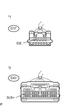
(a) Disconnect the D43 connector from the power management control ECU. |
 |
(b) Measure the resistance according to the value(s) in the table below.
Standard Resistance:
Tester Connection | Condition | Specified Condition |
|---|---|---|
D17-3 (IGE) - D43-8 (SLR+) |
Always |
Below 1 Ω |
D17-3 (IGE) - Body ground |
Always |
10 kΩ or higher |
*1 |
Front view of wire harness connector (to Steering Lock ECU (Steering Lock Actuator Assembly)) |
*2 |
Front view of wire harness connector (to Power Management Control ECU) |
| OK | | REPLACE POWER MANAGEMENT CONTROL ECU |
| NG | | REPAIR OR REPLACE HARNESS OR CONNECTOR |
Test yourself
A quick Toyota Venza quiz: every answer comes with an explanation and a link to the manual page.