4- cylinder injection engine(1.4 1 direct inction. turbocharger)
Removing and installing coolant pump
In this manual: 4- cylinder injection engine(1.4 1 direct inction. turbocharger)
~3min read
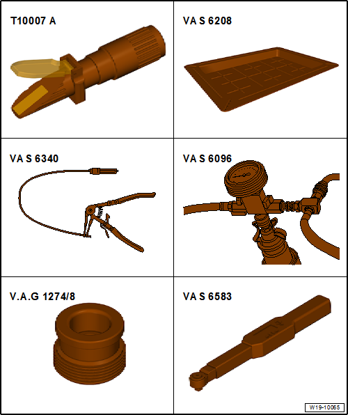
Special tools and workshop equipment required
Refractometer -T10007 A-
Drip tray for workshop hoist -VAS 6208-
Hose clip pliers -VAS 6340-
Cooling system charge unit -VAS 6096-
Adapter for cooling system tester -V.A.G 1274/8-
Torque wrench -VAS 6583-
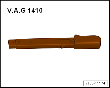
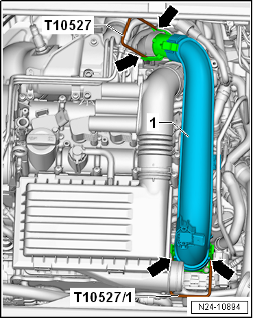
Torque wrench -V.A.G 1410-Release tool -T10527-Release tool -T10527/1-Removing
|
 |
|
 |
|
 |
|
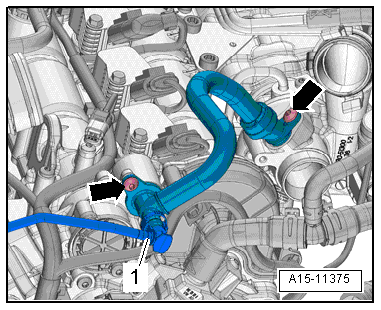 |
|
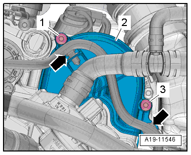 |
|
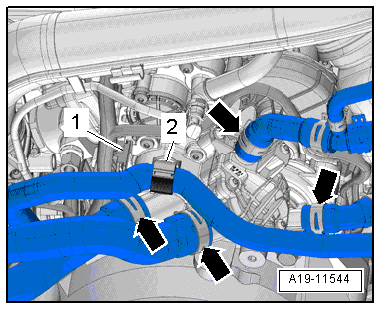 |
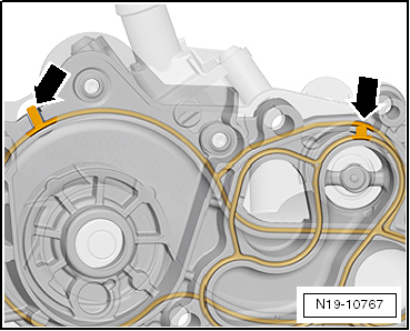
Installing Note Renew gasket for housing -arrows-.Renew the toothed belt of the coolant pump.Secure hose connections with hose clips meeting production standard → Electronic Parts Catalogue. |
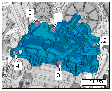 |
Note Always adhere to the sequence of work steps given below when installing the coolant pump. This ensures that the toothed belt is correctly tensioned.The following work steps must be carried out with the aid of a 2nd mechanic.
|
 |
|
|
| Stage | Bolts | Specified torque |
| 1 | -1 … 5- | Screw in to contact by hand |
| 2 | -1 … 5- | 10 N·m |
|
Note
For ease of handling, apply torque wrench -VAS 6583- vertically.
Note
Do not support torque wrench with your other hand.Do not apply »excessive force« to torque wrench.
|
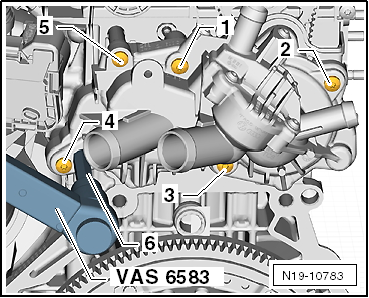 |
| Stage | Bolts | Specified torque |
| 3 | -2, 1, 5- | 10 N·m |
| 4 | -3, 4, 5, 1, 2- | 12 N·m |
Further installation steps are carried out in the reverse order; note the following: Coolant hose schematic diagram → Chapter.
Specified torquesTightening sequence for coolant pump → Anchor→ Chapter „Assembly overview - coolant pump, thermostat“→ Chapter „Assembly overview - turbocharger“→ Chapter „Assembly overview - charge air system“→ Electrical system; Rep. gr.27 |
Test yourself
A quick Volkswagen Golf quiz: every answer comes with an explanation and a link to the manual page.
Was this page helpful?