Constant Velocity (CV) Joint - Outer CV Joint
PROCEDURE
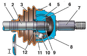
Outer Constant Velocity (CV) Joint 1 – clamp; 2 – driveshaft; 3 – dust boot; 4 – clamp; 5 – cage; 6 – outer race; 7 – small driveshaft; 8 – joint housing; 9 – snap ring; 10 – ball; 11 – conical ring; 12 – spring washer; I – position of spring washer during installation
For details on sofa cleaning, see the website.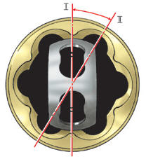
Position of Cage with Outer Race during Removal and Installation I – position of cage with outer race during removal; II – position of cage with outer race after installation and rotation (arrow)
Removal PROCEDURE 1. Remove the driveshaft from the vehicle (see subsection 7.2). 2. Clamp the driveshaft in a vise with soft jaws. 3. Remove clamps 7 and 9 (see Fig. Front Drive (models with 1.6 and 1.8 L engines)). 4. Slide dust boot 8 off the joint housing. 5. Drive CV joint 13 off the driveshaft using a soft-faced drift. 6. Remove snap ring 12. 7. Remove conical ring 11 and spring washer 10. 8. Remove dust boot 8. Disassembly WARNING Individual CV joint components must not be replaced. The CV joint is replaced only as an assembly. PROCEDURE 1. Wash the joint in kerosene.
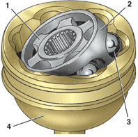
2. Mark the relative position of cage 2, outer race 1 and housing 4 on the end face. 3. Turn cage 2 and outer race 1 by lightly tapping the end of the cage with a soft-metal drift until ball 3 leaves the track. 4. Press ball 3 out of cage 2 with a soft-metal drift. 5. Press out the remaining balls in the same way. If the cage and outer race are jammed, carefully tap the joint housing. 6. Turn the cage with outer race perpendicular to the housing surface so that the two elongated windows of the cage align with the housing projections (position I), and remove the cage with outer race from the housing (see Fig. Position of Cage with Outer Race during Removal and Installation). 7. Push in one of the outer race projections by rotating it within the elongated window of the cage, and roll the outer race out. 8. Thoroughly wash all joint components in kerosene and inspect them, paying particular attention to the ground surfaces of the tracks and the spherical surfaces of the cage and balls.
WARNING Cracks, chips and signs of corrosion are not permitted. If the working surfaces of the tracks are worn by more than 0.1 mm, or any of the defects above are present, replace the joint as an assembly. Assembly PROCEDURE 1. Assemble the outer constant velocity joint in the reverse order of disassembly. Before assembly, pack 45 g of G-6.2 grease into the joint housing. 2. When assembling, observe the alignment marks made earlier. 3. After installing the cage with outer race into the joint housing, turn it to position II (see Fig. Position of Cage with Outer Race during Removal and Installation). 4. For convenience, insert the balls from opposite sides. Installation PROCEDURE 1. Install dust boot 8 onto the driveshaft (see Fig. Front Drive (models with 1.6 and 1.8 L engines)). 2. Install spring washer 12 (see Fig. Outer Constant Velocity (CV) Joint) and conical ring 11.
3. Install snap ring 12 (see Fig. Front Drive (models with 1.6 and 1.8 L engines)) or 9 (see Fig. Outer Constant Velocity (CV) Joint). 4. Drive the CV joint onto the driveshaft with a soft-faced drift so that outer race 6 snaps over snap ring 9. 5. Pack 45 g of G-6.2 grease into the joint. 6. Install dust boot 3 onto housing 8 of the joint. 7. Install clamp 4. 8. Lift the inner sealing lip of dust boot 3 slightly with a screwdriver before installing clamp 1, to equalize the pressure inside the joint. 9. Install clamp 1. 10. Check clamps 1 and 4 for cracks in the lock area.
WARNING If cracks are found, replace the clamps with new ones. The clamps must securely retain the dust boots on the sealing seats and ensure full sealing of the joints.
Test yourself
A quick Volkswagen Golf quiz: every answer comes with an explanation and a link to the manual page.