Constant Velocity (CV) Joint - Inner CV Joint
PROCEDURE
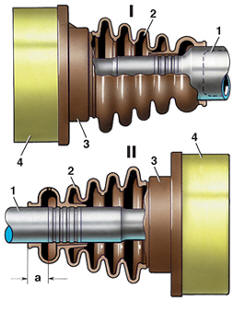
Installation of Dust Boot on GTi Models I – left driveshaft; II – right driveshaft; 1 – driveshaft; 2 – dust boot; 3 – cover; 4 – inner constant velocity (CV) joint
Removal PROCEDURE 1. Clamp the driveshaft in a vise with soft jaws. 2. Remove snap ring 1 (see Fig. Front Drive (models with 1.6 and 1.8 L engines)). 3. Mark the position of the end of dust boot 5 on the driveshaft with paint.
WARNING Do not make marks with sharp objects, as this will damage the protective lacquer coating.
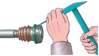
4. Remove clamps (models with 1.1 and 1.3 L engines). 5. Use a punch to knock the cover off the joint housing. 6. Press CV joint 2 (see fig. Front-Wheel Drive (models with 1.6 and 1.8 L engines)) off the driveshaft. 7. Remove spring washer 3. 8. Remove boot 5 with cover 4. Disassembly SEQUENCE OF OPERATIONS 1. Wash the joint in kerosene.
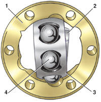
2. Mark the relative positions of cage 2, separator 3 and joint housing 1. 3. Turn cage 2 with separator 3 at right angles to housing 1 and remove them from the housing. 4. Remove balls 4.
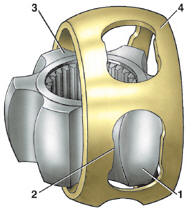
5. Turn cage 3 at right angles to separator 4, insert one of the cage projections 1 into the elongated window 2 of separator 4, and roll cage 3 out of the separator. 6. Thoroughly wash all joint parts in kerosene and inspect their condition, paying special attention to the ground raceway surfaces and the spherical surfaces of the separator and balls.
Warning Cracks, chips and signs of corrosion are not permissible. If the raceway working surfaces are worn by more than 0.1 mm or any of the above defects are present, replace the joint assembly. Assembly SEQUENCE OF OPERATIONS 1. Install cage 3 into separator 4. 2. Insert balls into the separator windows.
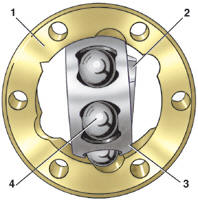
3. Insert separator 3 with cage 2 into joint housing 1 at right angles to housing 1, and turn separator 3 with cage 2 by 90° in accordance with the marks made earlier. 4. Check that the joint rotates freely. Installation SEQUENCE OF OPERATIONS 1. Mark distance a = 17 mm (fig. Installing boot on GTi models) on the driveshaft with paint or adhesive tape (GTi models only).
Warning On GTi models, the accuracy of boot installation is especially important. 2. Install boot 5 (see fig. Front-Wheel Drive (models with 1.6 and 1.8 L engines)) on the driveshaft with cover 4. 3. Install spring washer 3 with its concave side facing joint cage 2. 4. Press joint 2 onto the splines of driveshaft 6, applying force to the joint cage. 5. Install snap ring 1. 6. Pack the joint with 45 g of grease G-6.2 on each side. 7. Install cover 4 on joint housing 2. 8. Install the boot in accordance with the marks made earlier on the driveshaft. 9. Install clamps (for models with 1.1 and 1.3 L engines). 10. Install driveshaft (see subsection 7.2).
Test yourself
A quick Volkswagen Golf quiz: every answer comes with an explanation and a link to the manual page.