Axle shaft
PROCEDURE
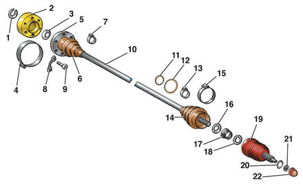
Front-wheel drive (models with 1.1 and 1.3 L engines) 1 – snap ring; 2 – inner constant velocity joint (CV joint); 3 – spring washer; 4 – clamp; 5 – cover; 6 – boot; 7 – clamp; 8 – stop; 9 – bolt; 10 – axle shaft; 11, 12 – O-rings; 13 – clamp; 14 – boot; 15 – clamp; 16 – spring washer; 17 – tapered ring; 18 – snap ring; 19 – outer constant velocity joint (CV joint); 20 – washer; 21 – nut; 22 – protective cap
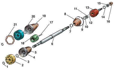
Front-wheel drive (models with 1.6 and 1.8 L engines) 1 – snap ring; 2 – inner constant velocity joint (CV joint); 3 – spring washer; 4 – cover; 5 – boot; 6 – axle shaft; 7 – clamp; 8 – boot; 9 – clamp; 10 – spring washer; 11 – tapered ring; 12 – snap ring; 13 – outer constant velocity joint (CV joint); 14 – washer; 15 – nut; 16 – protective cap; 17 – spring pin; 18 – torsional damper; 19 – boot (GTI model); 20 – cover (GTI model); 21 – gasket (GTI model)
Removal PROCEDURE 1. Apply parking brake. 2. Chock rear wheels with wedges.
Warning: With the axle shaft removed, do not move the vehicle, as the wheel hub bearing may be damaged without longitudinal load. 3. Pry off protective cap 22 from the wheel hub with a screwdriver (see figure Front-wheel drive (models with 1.1 and 1.3 L engines)). 4. Unscrew nut 21. 5. Remove washer 20. 6. Loosen wheel bolts. 7. Raise front of vehicle and support it on stands. 8. Remove wheels. 9. Unscrew bolts 9.
Warning: CV joint bolts attaching to the axle shaft flange have internal splined heads, so a special spline key is required to unscrew them. Do not use a hex key, as the splines may be damaged. 10. Disconnect inner CV joint from the axle shaft flange and remove the axle shaft from the wheel hub. If the axle shaft is difficult to remove from the hub, unscrew the ball joint bolt (see item 6 of subsection 9.1.5), push the suspension arm down and remove the axle shaft from the hub. 11. If necessary, remove gasket 21 (see figure Front-wheel drive (models with 1.6 and 1.8 L engines), GTI models).
WARNING On models with 1.6 and 1.8 L engines and diesel 1.6 L engines, a torsional vibration damper 18 is installed. When replacing the driveshaft, it must be transferred to the new driveshaft. 12. Drive out the spring pin 17. 13. Spread the ends of the torsional vibration damper 18 and remove it from driveshaft 6. Installation PROCEDURE 1. Check the condition of the adhesive tape on the inner surface of torsional vibration damper 18 and replace it with new tape if necessary. 2. Install torsional vibration damper 18 on the driveshaft in accordance with Fig. 7.3 (dimension a = 4 mm) and drive in a new spring pin 17 (see Fig. Front Drive (models with 1.6 and 1.8 L engines)). 3. Remove the protective film and bond a new gasket 21 into the inner CV joint (on GTi models). 4. Clean the splines of the hub and driveshaft of dirt and lubricate them with molybdenum grease. 5. Insert the driveshaft into the wheel hub. 6. Tighten bolts 9 (see Fig. Front Drive (models with 1.1 and 1.3 L engines)) to a torque of 45 N·m. 7. Install the wheel. 8. Lower the vehicle to the ground. 9. Tighten the wheel bolts to a torque of 110 N·m. 10. Install washer 20.
11. Tighten nut 21 to a torque of 230 N·m. 12. Install protective cap 22.
Test yourself
A quick Volkswagen Golf quiz: every answer comes with an explanation and a link to the manual page.