Transverse Links and Tie Rods, through MY 2010, FWD
Overview - Transverse Links and Tie Rods, through MY 2010, FWD
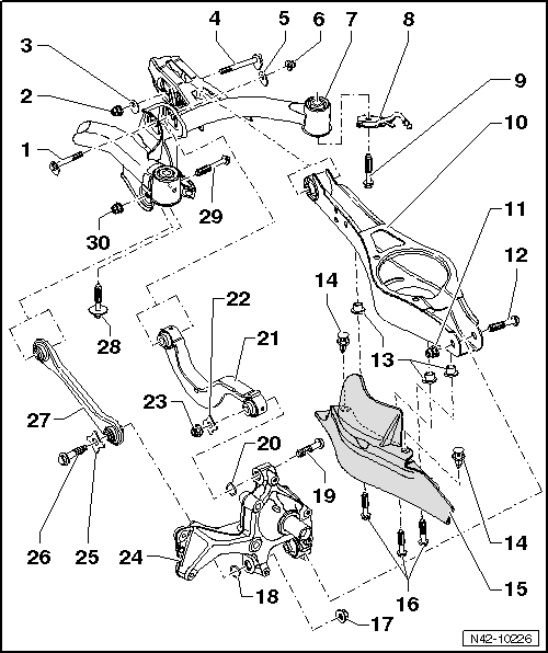
- Eccentric Bolt
- For camber setting
- Perform a vehicle alignment after loosening.
- Nut
- 95 N·m
- Always replace if removed
- M12 x 1.5
- Self-locking
- Always tighten the threaded connections in curb weight position.
- Eccentric Washer
- Inner bore with tab
- Eccentric Bolt
- For toe setting
- Perform a vehicle alignment after loosening.
- Eccentric Washer
- Inner bore with tab
- Nut
- 95 N·m
- Always replace if removed
- Self-locking
- M12 x 1.5
- Always tighten the threaded connections in curb weight position.
- Subframe
- Removing and installing.
- Servicing.
- Bracket for Rear Muffler
- Bolt
- 90 N·m +90º
- Always replace if removed
- M12 x 1.5 x 110
- Lower Transverse Link
- Removing and installing.
- Nut
- 90 N·m +90º
- Always replace if removed
- M12 x 1.5 x 75
- Self-locking
- Always tighten the threaded connections in curb weight position.
- Bolt
- Always replace if removed
- Threaded Rivet
- M6
- Expanding Rivet
- Stone Chip Protection
- Allocation. Refer to the Parts Catalog.
- Hex Bolt
- 8 N·m
- M6 x 12
- Nut
- Self-locking
- Always replace if removed
- Washer
- Bolt
- 130 N·m + 90º
- Always replace if removedM14 x 1.5 x 115
- Always tighten the threaded connections in curb weight position.
- Washer
- Upper Transverse Link
- Removing and installing.
- Washer
- Nut
- Self-locking
- Always replace if removed
- Always tighten the threaded connections in curb weight position.
- Wheel Bearing Housing
- Removing and installing.
- Washer
- Bolt
- 130 N·m + 90º
- Always replace if removed
- M14 x 1.5 x 115
- Always tighten the threaded connections in curb weight position.
- Tie rod
- There are different versions.
- Closed in direction of travel (the right and left tie rods are different)
- Opened downward (the right and left tie rods are the same)
- It is possible to interchange
- Pay attention to the allocation of the trailing arms when replacing them.
- Removing and installing.
- Bolt
- 90 N·m +90º
- M12 x 1.5 x 95
- Always replace if removed
- Bolt
- M12 x 1.5 x 90
- Always replace if removed
- Always tighten the threaded connections in curb weight position.
- Nut
- 90 N·m +90º
- Always replace if removed
- Self-locking
- Always tighten the threaded connections in curb weight position.
Overview - Left Rear Level Control System Sensor -G76-, FWD
Note
- Overview - Left Rear Level Control System Sensor -G76- Adaptive Chassis DCC, FWD.
- Vehicle level sensor is available as replacement part only complete with coupling rod and upper and lower retaining plates.
- Replacing with subframe installed.
- Headlamp Range Control Module -J431-
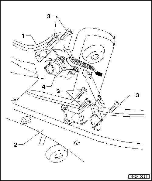
- Subframe
- Lower Transverse Link
- Bolt
- 5 N·m
- M5 x 20
- Left Rear Level Control System Sensor -G76-
- Complete with attachments
- Lever -arrow- must point toward vehicle exterior
- Replace in vehicle.
- After replacing, perform basic setting of the headlamps
Headlamps basic setting. Refer to Vehicle Diagnostic Tester, in "Guided Fault Finding" function.
Left Rear Level Control System Sensor -G76-, Removing and Installing
Note
Left Rear Level Control System Sensor -G76- for adaptive chassis DCC, FWD, Removing and installing.
Special tools and workshop equipment required
- Torque Wrench 1331 5-50Nm -VAG1331-
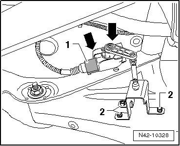
Removing
- Disconnect the connector -1-.
- Remove the bolts -2- from the lower transverse link.
- Remove bolts -arrows- from the subframe.
- Remove Left Rear Level Control System Sensor -G76-.
Installing
Install in reverse order of removal. Note the following:
The Left Rear Level Control System Sensor -G76- lever must point toward the outside of the vehicle.
- After replacing, perform a headlamp basic setting Vehicle Diagnostic Tester, in "Guided Fault Finding" function
Tightening Specifications
| Component | Tightening Specification |
| Left Rear Level Control System Sensor -G76- to lower transverse link and subframe | 5 N·m |
Upper Transverse Link, Removing and Installing
Special tools and workshop equipment required
- Torque Wrench 1332 40-200Nm -VAG1332-
Removing
- Remove the wheel.
- Remove coil spring.
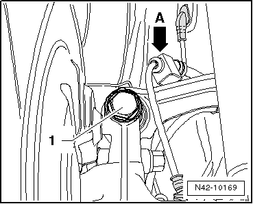
- Unhook speed sensor wiring -arrow A- from the upper transverse link.
- Remove the bolt -1-.
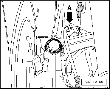
- Mark, for example using a felt-tip marker, position of eccentric bolt -arrow- to subframe.
- Remove the bolt -arrow-.
- Remove upper transverse link.
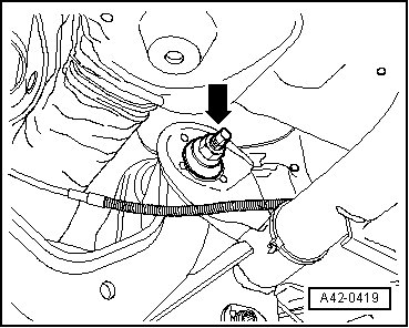
Installing
- Insert the upper transverse link into the vehicle and tighten the bolts by hand.
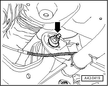
Only bolt on transverse link if dimension "a" is reached.
- Bolt upper transverse link to subframe and tighten new nut.
- Note applied marking of eccentric bolt -arrow- to subframe.
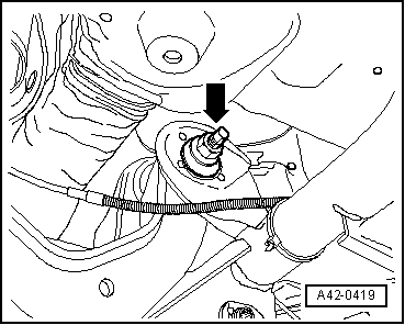
- Tighten the bolt -1- on the upper transverse link.
Note
Make sure that washer is installed between bolt and wheel bearing housing.
- Hook speed sensor wiring -arrow A- in at the upper transverse link.
- Install coil spring.
- Install the wheel and tighten.
- Perform vehicle alignment.
Tightening Specifications
| Component | Tightening Specification |
Upper transverse link to wheel bearing housing
|
130 N·m + 90º |
Upper transverse link to subframe
|
95 N·m
|
Lower Transverse Link, Removing and Installing
Special tools and workshop equipment required
- Torque Wrench 1332 40-200Nm -VAG1332-
Removing
- Measure dimension from wheel center to lower edge of wheel housing.
- Remove the wheel.
- Remove coil spring.
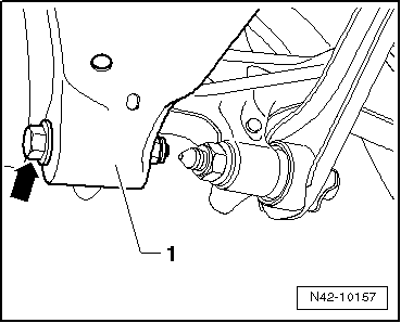
- Remove bolt -arrow- for lower transverse link -1-.
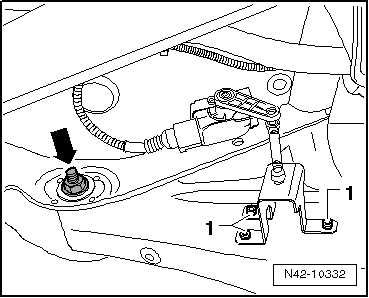
Vehicles with Automatic Headlamp Range Control
- Remove the bolts -1- from the lower transverse link.
Continuation for All Vehicles
- Mark, for example using a felt-tip marker, position of eccentric bolt -arrow- to subframe.
- Disengage rear exhaust system and lower.
- Remove the bolt -arrow-.
- Remove lower transverse link.
Installing
- Insert lower transverse link into vehicle and tighten the bolts by hand.
Only bolt on transverse link if dimension "a" is reached.
- Connect the upper transverse link to the subframe and tighten the new nut -arrow- to the tightening specification only.
- Note applied marking of eccentric bolt -arrow- to subframe.
- Suspend rear exhaust system.
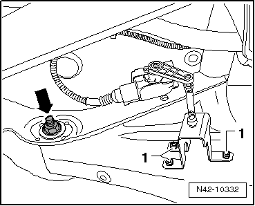
Vehicles with Automatic Headlamp Range Control
- Install the bolts -1- to the lower transverse link.
Continuation for All Vehicles
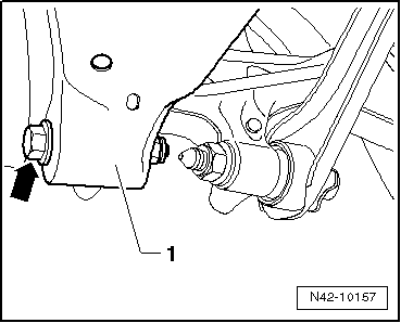
- Tighten bolt -arrow- for lower transverse link -1-.
- Install coil spring.
- Install the wheel and tighten.
- Perform vehicle alignment.
Tightening Specifications
| Component | Tightening Specification |
Lower transverse link to wheel bearing housing
|
90 N·m + 90º |
Lower transverse link to subframe
|
95 N·m |
| Left Rear Level Control System Sensor -G76- to lower transverse link | 5 N·m |
Tie Rod, Removing and Installing
Special tools and workshop equipment required
- Torque Wrench 1331 5-50Nm -VAG1331-
- Torque Wrench 1332 40-200Nm -VAG1332-
Removing
- Remove the wheel.
- Remove coil spring.
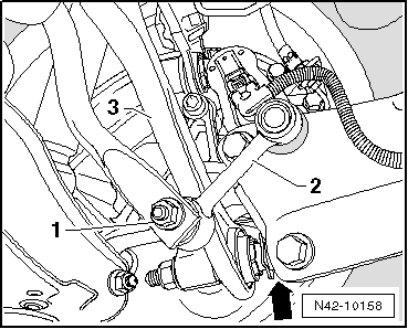
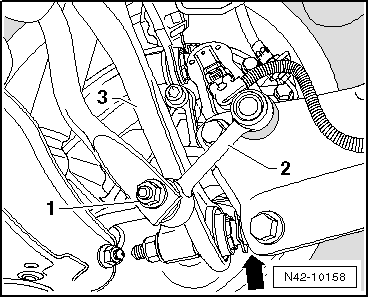
- Remove the nut -1- and pull the coupling rod -2- out of the stabilizer bar.
- Remove bolt -arrow- for tie rod -3-.
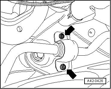
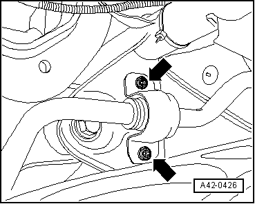
- Remove the bolts -arrows- for the stabilizer bar clamp.
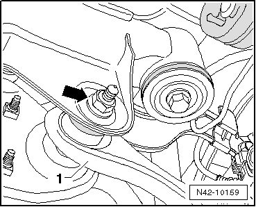
- Remove the nut -arrow- and remove bolt toward rear.
- Remove tie rod -1-.
Installing
Caution
- Pay attention to the different trailing arm versions when replacing the tie rod.
- Note the allocation of the tie rods for the trailing arms.
- Insert tie rod into vehicle and tighten the bolts by hand.
Note
Pay attention to the different versions of the tie rods: open underneath or closed in direction of travel.
The bolted connections of the tie rod must only be fastened when the dimension "a" is achieved.
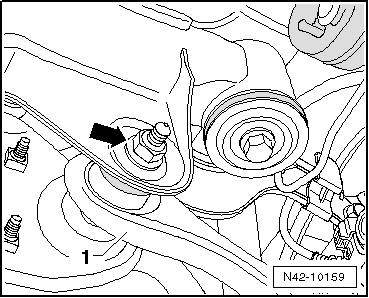
- Fasten the tie rod -1- to the subframe and tighten the new nut -arrow-.
- Tighten bolts -arrows- for stabilizer clamp.
- Tighten bolt -arrow- for tie rod -3-.
Note
Make sure that washer is installed between nut and wheel bearing housing.
- Insert coupling rod -2- into stabilizer and tighten nut -1-.
- Install coil spring.
- Install the wheel and tighten.
- Perform vehicle alignment.
Tightening Specifications
| Component | Tightening Specification |
Tie rod to steering knuckle
|
130 N·m + 90º |
Tie rod to subframe
|
90 N·m + 90º |
Stabilizer bar to subframe
|
25 N·m + 45º |
Stabilizer bar to coupling rod
|
40 N·m |
Tie Rods for Trailing Arms, FWD and AWD, Allocation
Note
The current production is now using the reinforced trailing arms. The old trailing arms are no longer available as a replacement part.
Trailing Arm Characteristics
- Standard trailing arm
- Reinforced trailing arm
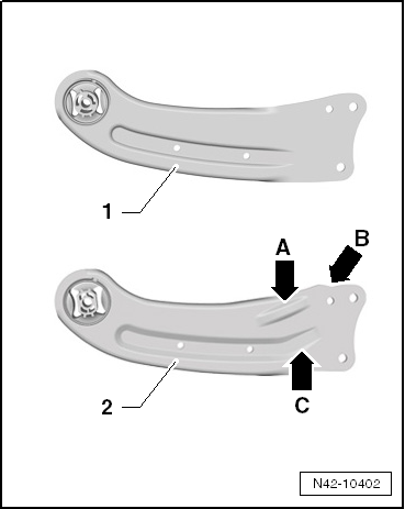
The reinforced trailing arm has the following distinguishing features:
Pfeil A - Additional reinforcement
Pfeil B - Additional opening
Pfeil C - Lengthened rib
- Interchanging the trailing arms is permitted
- Note the different tie rod versions when replacing the trailing arm.
- Allocation of the trailing arms to the tie rods.
Tie Rod Characteristics
- Reinforced tie rod closed in direction of travel
- Standard tie rod open downward
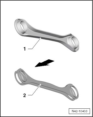
- The reinforced tie rod is different on the right and left sides.
- The standard tie rod is the same on the left and right sides.
- Arrow indicates direction of travel.
- Interchanging the tie rods is permitted
- Pay attention to the different trailing arm versions when replacing the tie rod.
- Allocation of the trailing arms to the tie rods.
Note the Allocation of the Tie Rods for the Trailing Arms .
Note
It is absolutely necessary to follow the allocation of the tie rods to the trailing arms. A different allocation is not permitted.
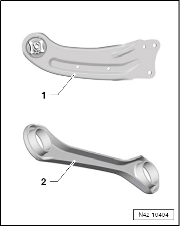
It is absolutely necessary that a reinforced tie rod -2- is installed when replacing a reinforced trailing arm -1-. If this is not the case, then the tie rod must be replaced.
Make sure a reinforced trailing arm -1- is installed in the vehicle when a reinforced tie rod -2- is being installed.
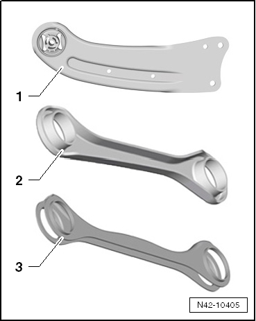
If a standard trailing arm -1- is being replaced, then it is permissible to install either tie rod version -2 or 3-.
If a standard trailing arm -1- is installed in the vehicle, then both versions of the tie rod can be installed.
Test yourself
A quick Volkswagen Tiguan quiz: every answer comes with an explanation and a link to the manual page.