Wheel Bearing Housing, Trailing Arm, AWD
Overview - Wheel Bearing Housing, Trailing Arm, AWD
The -arrow- points in the direction of travel.
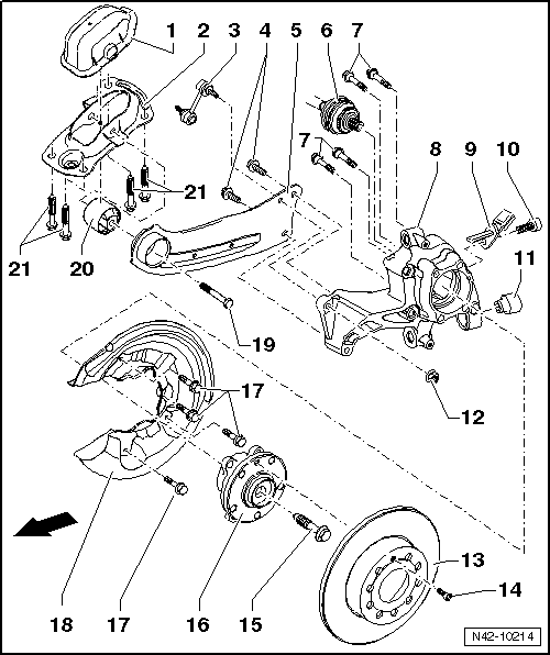
- Cover
- Mounting Bracket
- Coupling Rod
- Connects stabilizer to trailing link/wheel bearing housing
- Bolt
- 90 N·m + 45º
- Always replace if removed
- Observe the tightening sequence.
- Trailing Arm
- Different versions.
- Removing and installing.
- Servicing.
- Note the tie rod allocation when replacing them.
- Drive Axle
- Overview.
- Removing and installing.
- Internal Multi-Point Bolt
- 70 N·m + 90º
- Always replace if removed
- M14 x 1.5 x 45
- Wheel Bearing Housing
- Removing and installing.
- Right Rear ABS Wheel Speed Sensor -G44-/ Left Rear ABS Wheel Speed Sensor -G46-
- Can be checked in Guided Fault Finding using the Vehicle Diagnostic Tester.
- Before inserting the sensor, clean the inner surface of the hole and coat with Lubricant -G 000 650-.
- Hex Socket Bolt
- 8 N·m
- M6 x 16
- Bonded Rubber Bushing
- Replacing.
- Nut
- 45 N·m
- Always replace if removed
- M12 x 25
- Self-locking
- Brake Rotor
- Bolt
- 4 N·m
- Bolt
- Always replace if removed
- There are different versions.
WARNING
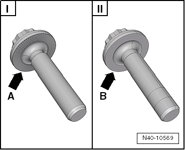
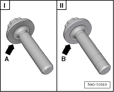
- There are two types of twelve-point bolts, with and without ribs. Distinguishing characteristics.
- When installing a twelve-point bolt, always check what type of twelve-point bolt is to be used.
- Use the correct tightening specification for the specific bolt.
- The tightening specification for a twelve-point bolt "with" ribs is 70 N·m + 90º.
- The tightening specification for a twelve-point bolt "without" ribs is 200 N·m + 180º.
- Allocation. Refer to the Parts Catalog.
- Wheel Hub with Wheel Bearing
- The ABS sensor ring is installed in the wheel bearing
- Removing and installing.
The wheel bearing and wheel hub are installed together in a housing.
This wheel bearing/hub unit is maintenance and adjustment free. Adjusting or servicing is not possible!
- Bolt
- 12 N·m
- M6 x 12
- Cover Plate
- Bolt
- 90 N·m +90º
- Always replace if removed
- M12 x 1.5 x 80
- Bonded Rubber Bushing
- Replacing.
- Bolt
- 50 N·m + 45º additional turn
- Always replace if removed
- M10 x 35
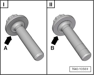
Difference Between A Twelve-Point Bolt with Ribs and A Twelve-Point Bolt without Ribs
The contact surfaces -arrow A- and -arrow B- are different on the two-point bolts.
- Twelve-point bolt with ribs -arrow A-
- Twelve-point bolt without ribs -arrow B-
Wheel Bearing Housing, Removing and Installing
Special tools and workshop equipment required
- Torque Wrench 1332 40-200Nm -VAG1332-
Removing
- Remove coil spring.
- Loosen the drive axle bolt on the wheel hub:
- Twelve-point bolt with ribs.
- Twelve-point bolt without ribs.
- Remove the wheel.
- Remove brake carrier and brake caliper and tie to body with wire.
- Remove ABS speed sensor from wheel bearing housing.
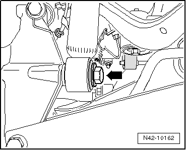
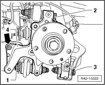
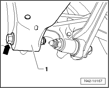
- Remove the bolt -arrow-.
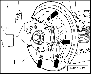
- Remove the bolts -arrows- and cover plate -1-.
- Remove bolt for tie rod -1-, upper transverse link -2- and lower transverse link -3- from wheel bearing housing -4-.
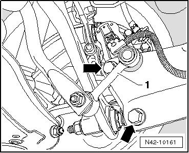
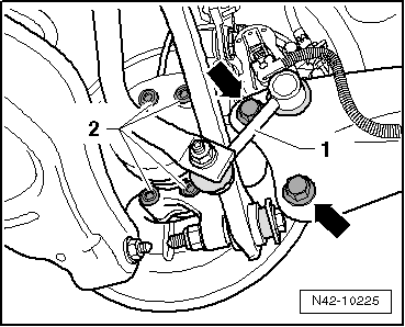
- Remove connecting link -arrow- from the wheel bearing housing.
- Pull the coupling rod -1- out of the trailing arm.
- Hold wheel bearing housing tightly and remove the bolts -arrows-.
- Remove the wheel bearing housing.
Installing
Install in reverse order of removal while noting the following:
Threaded Connector: Trailing Arm/Wheel Bearing Housing
Threaded connection of trailing link/wheel bearing housing must only be tightened when all other components (spring and strut always) of the respective wheel suspension have been already assembled. To tighten, suspension must be unloaded. Only now do the trailing link and wheel bearing housing move into the position required -arrows-.
- Install coil spring.
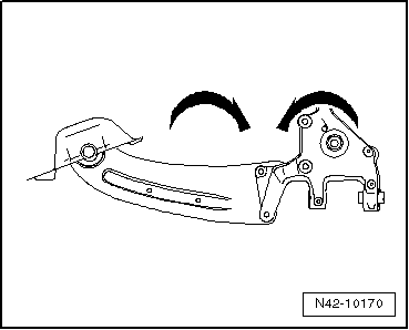
Always Perform the Following Work in the Sequence Given!
- Place trailing arm on wheel bearing housing with bolts -arrows- but do not tighten yet.
- Insert the coupling rod -1- into the trailing arm, but do not tighten the nut yet.
- Lower the suspension again using Engine and Gearbox Jack -VAS6931- and remove Engine/Gearbox Jack Adapter - Wheel Hub Support -T10149- from wheel hub.
- Tighten bolts -arrows- for longitudinal control arm to tightening specification, observe required position of components while doing so.
- Connect the coupling rod -1- to the wheel bearing housing and stabilizer bar.
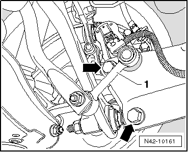
Bolting at wheel bearing housing may occur only when the dimension between wheel hub center and lower edge of wheel house, has been attained.
- Install the brake carrier with brake caliper.
- Tighten the drive axle bolt to wheel hub:
- Twelve-point bolt with ribs.
- Twelve-point bolt without ribs.
Caution
The vehicle must not be resting on the wheels when doing so.
When the bolt is loose, the wheel bearing can be damaged by the vehicle's weight.
Difference between A Twelve-Point Bolt with Ribs and A Twelve-Point Bolt without Ribs
The contact surfaces -arrow A- and -arrow B- are different on the two-point bolts.
- Twelve-point bolt with ribs -arrow A-
- Twelve-point bolt without ribs -arrow B-
- Install the wheel and tighten.
Tightening Specifications
| Component | Tightening Specification |
Wheel bearing housing to upper transverse link
|
150 N·m + 90º |
Wheel bearing housing to lower transverse link
|
90 N·m +90º |
Wheel bearing housing to tie rod
|
150 N·m + 90º |
Trailing arm to wheel bearing housing
|
90 N·m + 45º |
Connecting link to wheel bearing housing
|
45 N·m |
| Cover plate to wheel bearing housing | 12 N·m |
| ABS speed sensor to wheel bearing housing | 8 N·m |
| Shock absorber to wheel bearing housing. | 180 N·m |
| Brake rotor to wheel bearing housing | 4 N·m |
Drive axle to wheel hub "twelve-point bolt with ribs"
|
70 N·m + 90º |
Drive axle to wheel hub "twelve-point bolt without ribs"
|
200 N·m +180º |
Wheel Bearing Housing Bonded Rubber Bushing, Replacing
Special tools and workshop equipment required
- Bearing Installer - Control Arm -3346-
- Bearing Installer - Carrier Bearing -3350-
- Fitting Sleeve -3378-
- Torque Adapter -3390-
- Torque Wrench 1332 40-200Nm -VAG1332-
Removing
- Remove the wheel.
- Remove coil spring.
- Remove brake carrier and brake caliper and tie to body with wire.
Note
Do not allow brake caliper to hang from brake line.
- Remove the brake rotor bolt and the brake rotor.
- Remove cover plate.
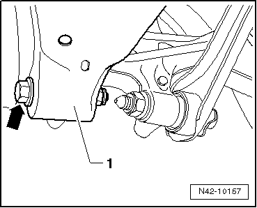
- Remove bolt -arrow- for lower transverse link -1-.
Pressing Out Bonded Rubber Bushing
- Attach tools as depicted in illustration.
- Bearing Installer - Control Arm - Nut -3346/3-
- Torque Adapter -3390-
- Bearing Installer - Carrier Bearing -3350-
- Nut, commercially available
- Bearing Installer - Control Arm - Spindle -3346/2-
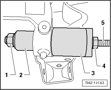
- Remove bonded rubber bushing by turning spindle.
Installing
Installing the Bonded Rubber Bushing
- Attach tools as depicted in illustration.
- Bearing Installer - Control Arm - Nut -3346/3-
- Bearing Installer - Control Arm -3346-
- Bonded rubber bushing
- Fitting Sleeve -3378-
- Nut, commercially available
- Bearing Installer - Control Arm - Spindle -3346/2-
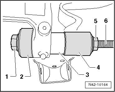
- Install bonded rubber bushing by turning support arm bearing installation tool.
Note
- Do not use lubricant!
- Insert bearing with care so it is not canted.
- Install cover plate.
- Install wheel bearing/wheel hub unit.
Bolting at wheel bearing housing may occur only when the dimension "a" has been obtained.
- Tighten bolt -arrow- for lower transverse link -1-.
- Install coil spring.
- Install the brake rotor.
- Install the brake carrier with brake caliper.
- Install the wheel and tighten.
Tightening Specifications
| Component | Tightening Specification |
Wheel bearing housing to lower transverse link
|
90 N·m +90º |
| Cover plate to wheel bearing housing | 12 N·m |
| Brake rotor to wheel bearing housing | 4 N·m |
Wheel Bearing and Wheel Hub, Removing and Installing
Special tools and workshop equipment required
- Torque Wrench 1332 40-200Nm -VAG1332-
- Torque Wrench 1410 -VAG1410-
Removing
- Remove coil spring.
- Remove the drive axle.
- Remove brake carrier and brake caliper and tie to body with wire.
Note
Do not allow brake caliper to hang from brake line.
- Remove the brake rotor bolt and the brake rotor.
- Remove the bolts -2-.
- Remove wheel hub/wheel bearing unit from wheel bearing housing.
Installing
Install in reverse order of removal while noting the following:
- Tighten the driveshaft bolt to wheel hub:
- Twelve-point bolt with ribs.
- Twelve-point bolt without ribs.
Caution
The vehicle must not be resting on the wheels when doing so.
When the bolt is loose, the wheel bearing can be damaged by the vehicle's weight.
Difference between A Twelve-Point Bolt with Ribs and A Twelve-Point Bolt without Ribs
The contact surfaces -arrow A- and -arrow B- are different on the two-point bolts.
- Twelve-point bolt with ribs -arrow A-
- Twelve-point bolt without ribs -arrow B-
Tightening Specifications
| Component | Tightening Specification |
Wheel hub with wheel bearing to wheel bearing housing
|
70 N·m + 90º |
| Brake rotor to wheel bearing housing | 4 N·m |
Trailing Arm with Mounting Bracket, Removing and Installing
Special tools and workshop equipment required
- Torque Wrench 1332 40-200Nm -VAG1332-
- Engine/Gearbox Jack Adapter - Wheel Hub Support -T10149-
Removing
- Remove the wheel.
- Remove coil spring.
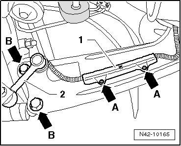
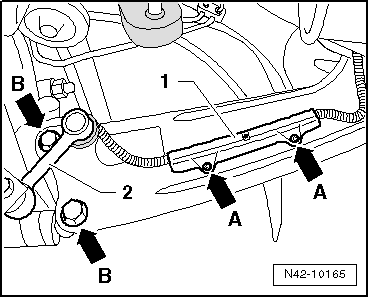
- Remove retainer -1-, pressing out inner pins of rivets -arrows A-.
- Remove the coupling rod -2- from trailing arm.
- Remove bolts -arrows B-.
- Unclip electrical wire from mounting bracket.
- Mark installation position of mounting bracket on body.
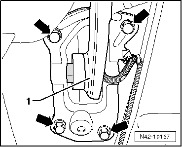
- Remove the bolts -arrows-.
- Remove longitudinal control arm -1- with mounting bracket.
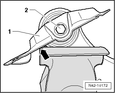
If longitudinal control arm is being replaced, mounting bracket must be removed from longitudinal control arm.
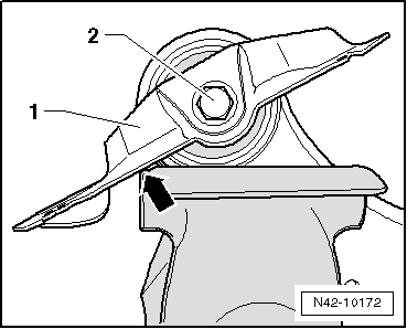
- To do so, clamp longitudinal control arm into vise so that mounting bracket -1- makes contact at vise -arrow-.
- Remove the bolt -2-.
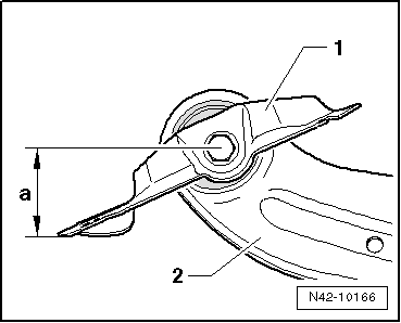
Installation position of mounting bracket to trailing link must then be adjusted.
Determining Installation Position of Mounting Bracket Relative to Trailing Arm
Measure dimension -a- from center of bolt to outer edge of mounting bracket.
Dimension -a- is 57.5 +-1 mm.
- Mounting bracket
- Trailing arm
- When dimension -a- has been adjusted, tighten bolt.
Installing
Caution
Note the different tie rod versions when replacing the trailing arm.
Note the allocation of the tie rods for the trailing arms.
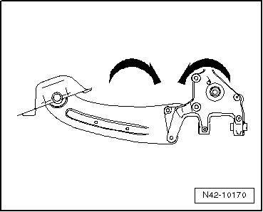
Threaded Connector: Trailing Arm/Wheel Bearing Housing
Threaded connection of trailing link/wheel bearing housing must only be tightened when all other components (spring and strut always) of the respective wheel suspension have been already assembled. To tighten, suspension must be unloaded. Only now do the trailing link and wheel bearing housing move into the position required -arrows-.
- Install coil spring.
Always perform the following work in the sequence given!
- Attach longitudinal control arm and mounting bracket with bolts -arrows- to wheel bearing housing, but do not tighten.
- Insert the coupling rod -1- into the trailing arm, but do not tighten the nut yet.
- Raise the suspension using Engine and Gearbox Jack -VAS6931- and Engine/Gearbox Jack Adapter - Wheel Hub Support -T10149- until the mounting bracket contacts the body.
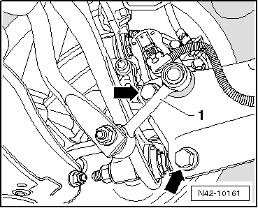
- Tighten bolts -arrows- on old impression.
- Lower the suspension again using Engine and Gearbox Jack -VAS6931- and remove Engine/Gearbox Jack Adapter - Wheel Hub Support -T10149- from wheel hub.
- Install coil spring.
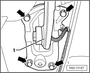
- Tighten bolts -arrows B- for longitudinal control arm to tightening specification, observe required position of components while doing so.
- Tighten the coupling rod nut -2- to the wheel bearing housing.
- Install retainer -1-, pressing in inner pins of rivets -arrows A-.
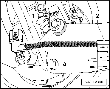
- When installing the wires for the electrical parking brake, make sure the dimension -a- between the connector -1- and the retainer -2- is exact.
Dimension -a- = 150 mm
- Install the wheel and tighten.
- Perform vehicle alignment.
Tightening Specifications
| Component | Tightening Specification |
Trailing arm to wheel bearing housing
|
90 N·m + 45º |
Trailing arm to mounting bracket
|
90 N·m +90º |
Mounting bracket to body
|
50 N·m + 45º |
Coupling rod to trailing arm
|
45 N·m |
Trailing Arm, Servicing
Special tools and workshop equipment required
- Press Plate -VW401-
- Press Plate -VW402-
- Front Subframe Mount Kit -3372-
- Hydraulic Press - Bushing Assembly Tool Kit -T10230-
Pressing Out the Bonded Rubber Bushing
- Remove trailing link.
- Clamp longitudinal control arm into vise so that mounting bracket -1- makes contact at vise -arrow-.
- Remove the bolt -2-.
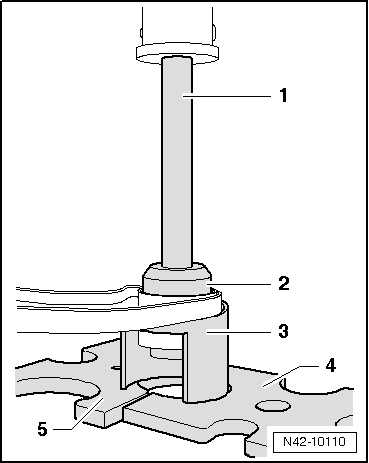
- Install tools as shown in the illustration.
- Hydraulic Press - Bushing Assembly Tool Kit-Pipe -T10230/3-
- Hydraulic Press - Bushing Assembly Tool Kit-Press Piece -T10230/10-
- Front Subframe Mount Kit -3372-
- Press Plate -VW401-
- Press Plate -VW402-
- Press out the bonded rubber bushing.
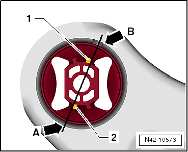
Position the bonded rubber bushing as follows:
- Install a connection line between the gap -arrow A- and the recess -arrow B-, for example, with a straight edge.
- Align the bonded rubber bushing so that the upper right tab -1- is to the left of the line.
- The lower left tab -2- must be located on the right of the connection line.
Note
Always make sure that the bonded rubber bushing is in the correct installation position to the trailing arm bushing.
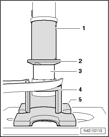
- Install tools as shown in the illustration.
- Hydraulic Press - Bushing Assembly Tool Kit - Tube -T10230/5-
- Hydraulic Press - Bushing Assembly Tool Kit-Thrust Plate -T10230/12-, the chamfer must face the bonded rubber bushing
- Bonded rubber bushing
- Front Subframe Mount Kit -3372-
- Press Plate -VW402-
- Press in bonded rubber bushing flush.
- Install the mounting bracket on trailing arm.
- Install the trailing arm.
Test yourself
A quick Volkswagen Tiguan quiz: every answer comes with an explanation and a link to the manual page.