Axle beam
Assembly overview - Axle beam

Note
- Welding and straightening work on load-bearing and wheel-guiding components of the wheel suspension is not permitted.
- Always replace self-locking nuts.
- Always replace corroded bolts/nuts.
- Rubber-metal bearings have a limited rotation range. Therefore, only tighten the bolted connections on components with rubber-metal bearings once the wheel bearing housing is raised (unladen position).
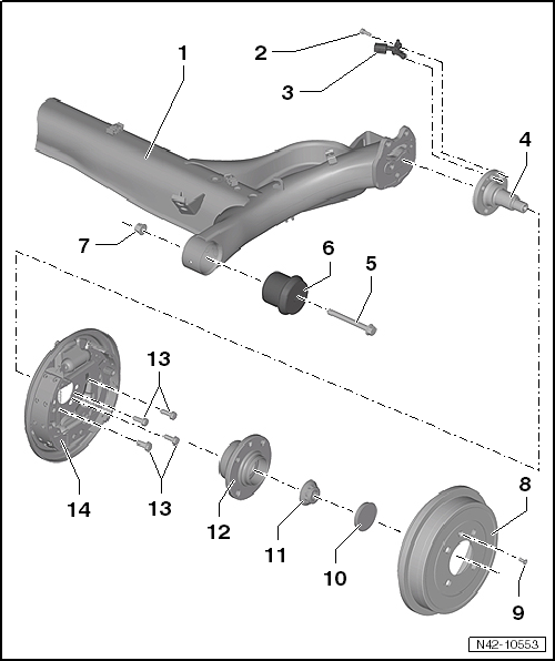
- Axle beam
- Contact surface and threaded holes for stub axle free of paint and dirt
- Remove and install
- Bolt
- 8 N·m
- ABS speed sensor
- Before inserting the sensor, clean the inner surface of the bore and coat it with solid lubricant paste -G 000 650-.
- Stub axle
- Straightening work is not permitted!
- Re-cutting threads is not permitted!
- Bolt
- Turn a further 180º after 50 N·m
- insert from outside
- replace after every removal
- tighten in unladen position
- Rubber-metal bushing
- Remove and install
- Nut
- Self-locking
- replace after every removal
- Brake drum
- Bolt
- 8 N·m
- Dust cap
- replace after every removal
- press out and drive in
A proper seal is only achieved with a new dust cap.
Only then is optimum function and long service life of the wheel bearing ensured.
- Twelve-point nut
- Self-locking
- Turn a further 30º after 70 N·m
- replace after every removal
- Wheel bearing unit
- the ABS sensor ring is installed in the wheel hub
- Remove and install
The wheel bearing and wheel hub are integrated together in one housing.
The wheel hub with wheel bearing is maintenance-free and requires no play adjustment. Adjustment and repair work is not possible!
- Bolt
- Turn 30 N·m and then a further 90º
- replace after every removal
- with disc spring
- Brake backing plate with brake shoes
Replace rubber-metal bearing for axle beam
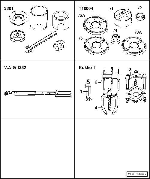
Required special tools, testers and equipment, and auxiliary items
- Installation device -3301-
- Assembly tool -T10064-
- Torque wrench -V.A.G 1332-
- -2- Puller -Kukko 18-2-
- -3- Separator -Kukko 15-2-
Carry out the following work:
Removing
- Lower rear axle.
- Attach and tension separator, e.g. -Kukko 15-2- to the collar of the bearing.
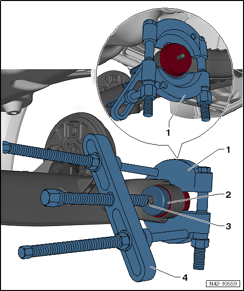
- Install the remaining tools as shown in the illustration and press out the bearing.
- 1 - Separator, e.g. -Kukko 15-2-
- 2 - Pressure piece -3292/3-
- 3 - Bolt for axle beam
- 4 - Puller, e.g. -Kukko 18-2-
Installing
- Observe the installation position of bearing -1- to axle beam -2-.
The notch -arrow A- of bearing -1- must point to the eye -arrow B- of axle beam -2-.

- Position bearing -2- on axle beam in installation position and install the tools as shown in illustration -I-.
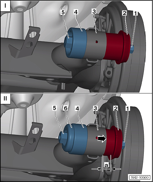
- Spindle -3301/1-
- Bearing
- Axle beam
- Pressure piece -T10064/2-
- Nut -3301-
- Draw bearing -2- into axle beam until distance -a- remains.
-a = 10 mm
- Remove nut -3301--5- and install thrust bearing -3301--6- as shown in illustration -II-.
- Draw bearing -2- into axle beam -3- as far as the stop -arrow-.
Installation is carried out in reverse order.
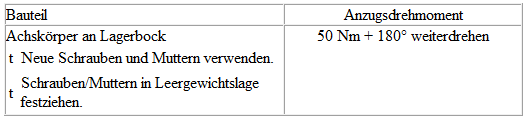
- Tighten rear axle in unladen position.
- Install wheels and tighten.
Tightening torques