Pistons and connecting rods
Assembly overview - Pistons and connecting rods
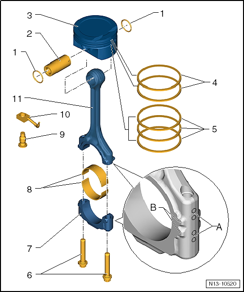
- Circlip
- Piston pin
- If stiff, heat the piston to 60 °C
- Remove and install using driver -10 - 14-
- Piston
- Check "Checking pistons and cylinder bore"
- Mark installation position and cylinder assignment
- Arrow on piston crown points toward pulley side
- Install with piston ring compressor strap
- Compression rings
- Offset ring gaps by 120°
- Remove and install compression rings using piston ring pliers
- "TOP" marking faces piston crown
- Check ring end gap "Checking pistons and cylinder bore"
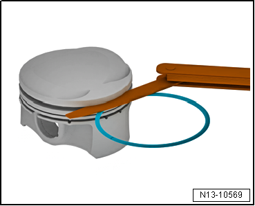
- Check ring side clearance "Checking pistons and cylinder bore"
- Oil control rings
- Carefully remove and install 3-piece oil control rings by hand
- Check ring end gap "Checking pistons and cylinder bore"
- Ring side clearance not measurable
- Connecting rod bolt
- Oil threads and contact surface
- For radial clearance measurement, tighten to the specified tightening torque, but do not turn further
- replace after removal
- 30 N·m +90º
- Connecting rod bearing cap
- Because the connecting rod is separated by the cracking process, the cap fits only in one position and only on its associated connecting rod.
- Mark cylinder assignment before removal -A-
- Installation position: mark -B- faces pulley side (if no mark is present, mark before removal)
- Bearing shell
- Do not interchange used bearing shells
- Insert bearing shells centrally
Measure radial clearance with Plastigage:
New: 0.020 ... 0.060 mm Wear limit: 0.070 mm When measuring radial clearance, do not turn the crankshaft- Bolt with pressure relief valve
- Opening pressure of pressure relief valve: 1.8 ... 2.2 bar
- 27 N·m
- Oil spray nozzle
- for piston cooling
- Connecting rod
- replace only as a set
- Mark cylinder assignment -A-
- Installation position: mark -B- faces pulley side (if no mark is present, mark before removal)
- Axial guidance by piston
Checking pistons and cylinder bore
Check piston
Required Special Tools, Test and Measuring Equipment and Auxiliary Items
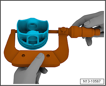
- Micrometer 50 - 75 mm -VAS 6070-
- Measure with outside micrometer approx. 10 mm up from lower edge, offset 90° to piston pin axis.
- Maximum deviation from nominal dimension: -0.04 mm.

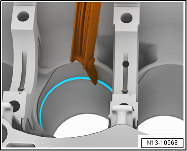
Checking piston ring end gap
- Insert ring squarely from top into lower cylinder opening, approx. 15 mm from cylinder edge.
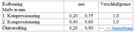
1) No wear limit specified
Checking piston ring side clearance
Clean ring groove before checking.

Measuring cylinder bore
Required Special Tools, Test and Measuring Equipment and Auxiliary Items
- Internal micrometer -VAS 6078-
- Measure with internal micrometer -VAS 6078- at 3 points, crosswise in transverse direction -A- and in longitudinal direction -B-.
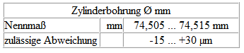
Maximum deviation from nominal size: 0.08 mm.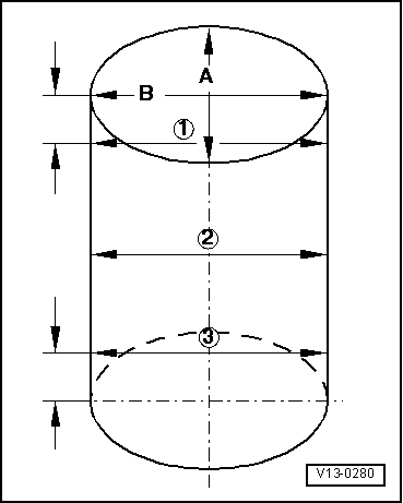
Separating new connecting rod
On new connecting rods, the predetermined breaking point may not be fully broken through. If the connecting rod bearing cap cannot be removed by hand, proceed as follows:
- Mark cylinder assignment of connecting rod.
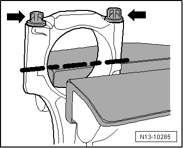
- Clamp connecting rod lightly in a vise with aluminum protective jaws, as shown in illustration.

Note
- Clamp connecting rod only lightly to avoid damaging it.
- Clamp connecting rod below the dashed line.
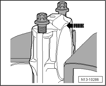
- Unscrew the two bolts -arrows- approx. 5 turns.
- Carefully strike connecting rod bearing cap in direction of arrow with plastic hammer until loose.
Tightening torque
- Connecting rod bearing cap bolts "Assembly overview - pistons and connecting rods"