Cylinder block, transmission side
Assembly overview - Cylinder block, transmission side

- Engine speed sensor -G28-
- Remove and install
- 5 N·m
- Connector
- Sealing flange with sensor wheel and seal
- Replace sealing flange only complete with seal and sensor wheel
- Remove and install
- Bolt
- 8 N·m
- Flywheel
- Bolt
- replace after removal
- 60 N·m +90º
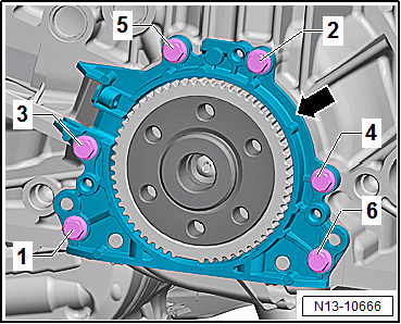
Transmission side sealing flange - tightening torque and sequence
- Tighten bolts -1- to -6- in stages in the following sequence:

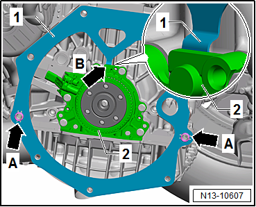
Installing intermediate plate
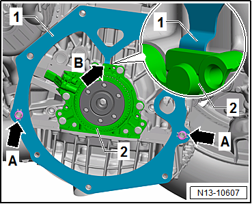
- Hook intermediate plate -1- onto sealing flange -2- -arrow B-.
- Slide intermediate plate onto locating sleeves -arrows A-.
Removing and installing flywheel
Required Special Tools, Test and Measuring Equipment and Auxiliary Items
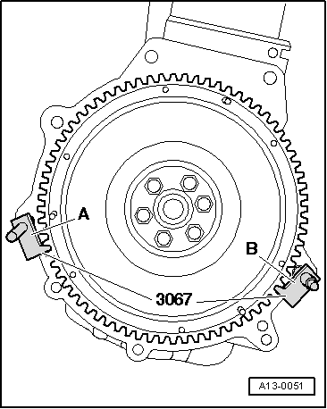
- Counterholder -3067-
Removing
- Transmission removed

- Insert counterholder -3067- into the bore in the cylinder block -pos. B-.
- Loosen and remove flywheel bolts.
Installing
Installation is carried out in the reverse order, observing the following:

Note
- Replace bolts that are tightened using an angle-of-rotation method.
- The flywheel with sensor wheel can only be installed in one position.
- Insert counterholder -3067- into the bore in the cylinder block -pos. A-.
Tightening torques
- "Assembly overview - Cylinder block, transmission side"
Removing and installing transmission side sealing flange
Required Special Tools, Test and Measuring Equipment and Auxiliary Items
- Open-ended wrench -V.A.G 1332/11-

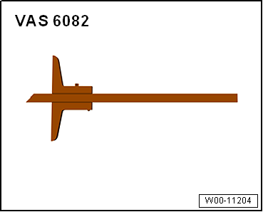
- Depth gauge vernier caliper -VAS 6082-
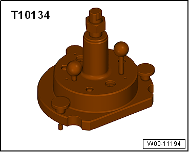
- Installation tool -T10134-
- Locking bolt -T10340-
- 3x bolt M6x35.
- Spark plug socket, e.g. -3122 B-
- Screwdriver with a shaft length of at least 250 mm
- Hex key
- Work sequence

Note
For clarity, the procedures are shown with the engine removed.
- Remove transmission.
- Remove clutch.
- Remove flywheel, see "Removing and installing flywheel".

- Lift intermediate plate -1- off the locating sleeves -arrows A-.
- Guide intermediate plate -1- upward.
- Pull retaining lug -arrow B- of intermediate plate -1- out of the recess behind the sealing flange.
- Unscrew blanking plug from the "TDC" bore in the cylinder block.
- Screw locking bolt -T10340- into the cylinder block as far as it will go and tighten to 30 N·m.
- Turn crankshaft in the direction of engine rotation until it stops.
- The locking bolt now rests against the crankshaft web.

Note
Locking bolt -T10340- only locks the crankshaft in the direction of engine rotation.
- Remove oil pan, see "Removing and installing oil pan".
- Remove engine speed sensor -G28- -arrow-, see "Removing and installing engine speed sensor -G28-".

- Unscrew bolts -arrows- for sealing flange -1-.
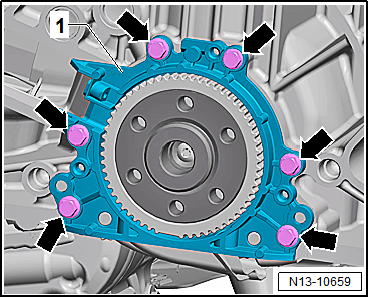
- To press off, screw 3 bolts M6x35 into sealing flange -1- -arrows-.

Note
Sealing flange -1- is pressed off the crankshaft -3- together with sensor wheel -2-.
- Screw in the bolts alternately, turning each by no more than 1/2 turn at a time.
- Remove sealing flange -1- together with sensor wheel -2-.
Pressing in sealing flange with sensor wheel

Note

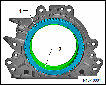
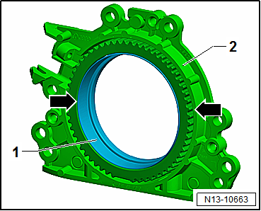
- Sealing flange -2- with PTFE seal is fitted with a sealing lip support ring -3-. This support ring functions as an installation sleeve and must not be removed before installation.
- Sealing flange -2- and sensor wheel -3- must not be separated after removal from the spare parts packaging.
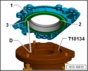
- Sensor wheel -3- is positioned by locating it on the locating pin of installation tool -T10134-.
- Sealing flange and seal are one unit and may only be replaced together with the sensor wheel.
- Installation tool -T10134- is positioned relative to the crankshaft by a guide pin, which is inserted into a bore in the crankshaft.
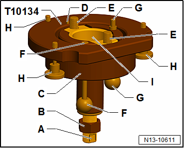
Design of installation tool -T10134-:
- Clamping surface
- Nut
- Installation bell
- Locating pin
- Hex socket head bolt (2 pieces)
- Guide pin for gasoline engines (red handle)
- Guide pin for diesel engines (black handle)
- Knurled screws (3 pieces)
- Inner part
Attaching sealing flange with sensor wheel to installation tool -T10134-:
- Turn nut -B- onto threaded spindle until just before clamping surface -A-.
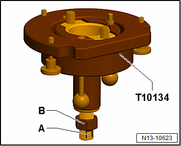
- Clamp installation tool -T10134- in a vise -1- by clamping surface -A- of threaded spindle.
- Press installation sleeve -C- down until it rests on nut -B-.
- Inner part of the installation tool and installation sleeve must be on the same level.

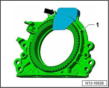
- If fitted, remove the retaining clip -arrow- from the new seal flange.

Note
Do not turn the sender wheel or remove it from the seal flange.
- Place seal flange -1- front side down on a clean, flat surface.
- Press sealing lip support ring -2- down in the direction of the -arrow- until it rests on the flat surface.
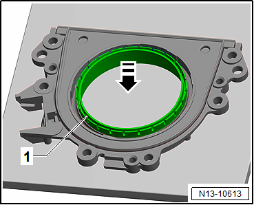
- Upper edge of sealing lip support ring -1- and front edge of seal flange -2- must be aligned -arrows-.
- Place seal flange -1- front side onto installation tool -T10134- so that locating pin -D- engages in hole -3- of sender wheel -2-.
- The seal flange must rest flat on the installation tool.
- Screw knurled screws -H- onto seal flange -1-.
- Press seal flange -1- and sealing lip support ring -2- onto the surface of installation tool -T10134- while tightening.
- This prevents the locating pin from slipping out of the hole in the sender wheel.
- Make sure the sender wheel remains secured in the installation tool while fitting the seal flange.

Fasten installation tool -T10134- with seal flange -1- to crankshaft flange:
- Crankshaft flange must be free of oil and grease.
- Engine is at "TDC".
- Turn nut -B- as far as the end of the threaded spindle.
- Press threaded spindle of installation tool -T10134- in the direction of the -arrow- until nut -B- contacts installation sleeve -C-.
- Align flattened side of installation sleeve with the oil pan side sealing surface of the cylinder block.

- Fasten installation tool -T10134- together with seal flange -1- to crankshaft flange -2-.
- To do this, screw socket head cap screws -E- into the crankshaft flange by about 5 threads using a hex key.
- Insert guide pin for petrol engines (red handle) -F- into the crankshaft flange.
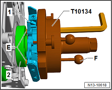
- Screw 2 bolts M6x35 -3- into cylinder block -2- to guide seal flange -1-.
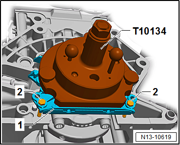
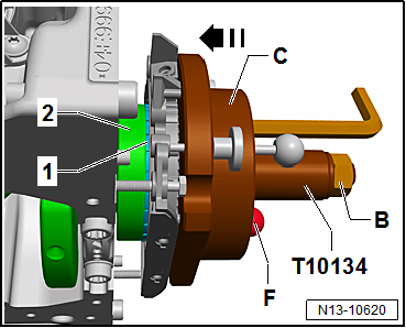
Bolt installation tool -T10134- to crankshaft flange:
- Push installation sleeve -C- by hand in the direction of the -arrow- until sealing lip support ring -1- contacts crankshaft flange -2-.
- Check that the guide pin for petrol engines (red handle) -F- is correctly seated in the hole of the crankshaft. This gives the sender wheel its final installed position.

Note
The guide pin for diesel engines (black handle) must not be inserted into the threaded hole of the crankshaft.
- Tighten both socket head cap screws of the installation tool finger-tight.
- Turn nut -B- by hand onto the threaded spindle until it contacts installation sleeve -C-.
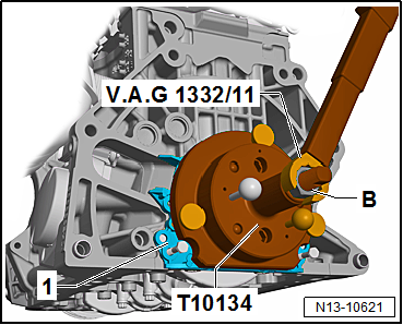
Press sender wheel onto crankshaft flange using installation tool -T10134-:
- Tighten nut -B- of installation tool -T10134- to 35 N·m.
- After tightening the nut to 35 N·m, a small air gap must still remain between cylinder block -2- and seal flange -1-.
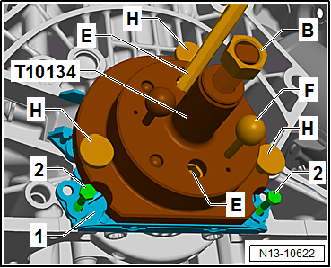
Check installed position of sender wheel on crankshaft:
- Turn nut -B- as far as the end of the threaded spindle.
- Unscrew both bolts -2- from the cylinder block.
- Pull guide pin for petrol engines (red handle) -F- out of the crankshaft flange.
- Unscrew knurled screws -H- from seal flange -1-.
- Unscrew installation tool -T10134- from crankshaft flange by removing socket head cap screws -E- from crankshaft flange.
- Remove sealing lip support ring.
- Place depth gauge VAS 6082 on crankshaft flange -2-.
- Measure the distance between crankshaft flange -2- and sender wheel -1-.
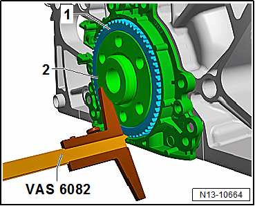
- Measure distance -a- between crankshaft flange -2- and sender wheel -1-.
- Specified value: dimension -a- = 0.5 mm.
- If the specified value is too small, press sender wheel further on.
- When the specified value is reached, complete the remaining assembly.

Press sender wheel further on:
- Fasten installation tool -T10134- to crankshaft flange -2-.
- Make sure the locating pin of installation tool -T10134- engages in the hole of the sender wheel.
- Tighten socket head cap screws -E- finger-tight.
- Push installation tool -T10134- by hand onto seal flange -1-.
- Turn nut -B- by hand onto the threaded spindle until it contacts installation tool -T10134-.
- Insert guide pin for petrol engines (red handle) -F- into the crankshaft flange.
- Screw knurled screws -H- into seal flange -1-.
- Screw 2 bolts M6x35 -2- into the cylinder block to guide the seal flange.
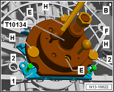
- Tighten nut -B- of installation tool -T10134- to 40 N·m.
- Check the installed position of the sender wheel on the crankshaft again.
- If the specified value is too small, tighten nut of installation tool -T10134- to 45 N·m.
- Check the installed position of the sender wheel on the crankshaft again.
Assembly
- Tighten bolts for seal flange on vehicles with manual transmission.
- Install oil pan "Removing and installing oil pan".
- Install adapter plate on vehicles with manual transmission.
- Install flywheel on vehicles with manual transmission "Removing and installing flywheel".
Tightening torques
- ""Seal flange, transmission side - tightening torque and sequence""
- "Assembly overview - Cylinder block, transmission side"
- "Assembly overview - Ignition system"
- → Body assembly work, exterior.

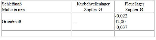
Crankshaft
Crankshaft dimensions
Risk of distortion of the main bearing saddles. The crankshaft must not be removed. Even loosening the crankshaft main bearing cap bolts distorts the main bearing saddles of the cylinder block. These distortions reduce the bearing clearance. Even if the bearing shells are not replaced, bearing damage can occur due to changed bearing clearance. If the main bearing cap bolts have been loosened, the cylinder block must be replaced complete with the crankshaft.
Measuring crankshaft bearing clearance is not possible with workshop equipment.