Clutch Actuation
Component location overview - clutch actuation
Component location overview - clutch actuation, up!
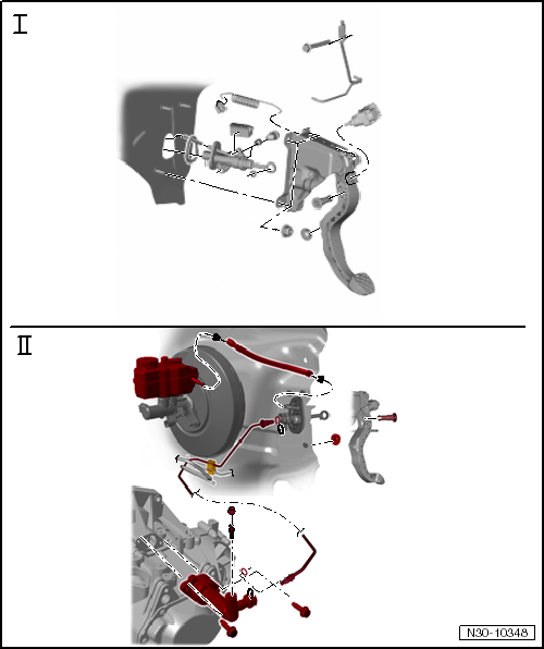
- "Assembly overview - pedal assembly, up!"
- "Assembly overview - clutch hydraulics"
Assembly overview - pedal assembly
Assembly overview - pedal assembly, up!
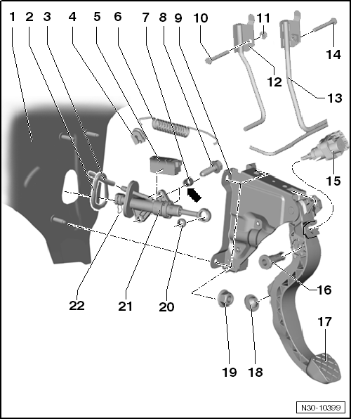
- Front Panel
- with seat for bearing bracket and clutch master cylinder
- Gasket
- glue to clutch master cylinder
- compensating hose
- Replace
- Socket
- insert into bearing bracket, install tension spring
- installation position does not need to be observed
- Clutch position sensor -G476-
- installed depending on production status
- can be checked in Guided Fault Finding with the → Vehicle Diagnostic Tester
- Assignment → Electronic Parts Catalog (ETKA)
- Remove and install
- Tension spring
- is hooked into the bearing bracket and the clutch pedal
- Remove and install
- Bushing
- 2 pieces
- Chamfer -arrow- points toward clutch master cylinder
- press in flush
- Bolt
- 13 N·m
- Bearing bracket with clutch pedal
- Remove and install
- Bolt
- Left-hand drive
- for crash strut on steering column
- 20 N·m
- Hex nut
- Left-hand drive
- for crash strut on steering column
- Crash brace
- Left-hand drive
- is attached to the steering column
- Assign components via the → Electronic Parts Catalog (ETKA)
- Crash brace
- Right-hand drive
- is attached to the steering column
- Assign components via the → Electronic Parts Catalog (ETKA)
- Bolt
- Right-hand drive
- for crash strut on steering column
- 20 N·m
- Clutch pedal switch -F36-
- installed depending on production status
- Assign components via the → Electronic Parts Catalog (ETKA)
- Remove and install
- Bearing pin
- for plunger/clutch master cylinder
- replace after removal
- Cap
- Bump stop
- for the clutch pedal
- Hex nut
- 3 pcs.
- Self-locking
- replace after removal
- 25 N·m
- Bearing bush
- Remove and install
- Clutch master cylinder
- Remove and install
- Clip
- To remove the line between clutch master cylinder and clutch slave cylinder, pull clip out to stop
Assembly overview - clutch hydraulics
Assembly overview - clutch hydraulics, up!
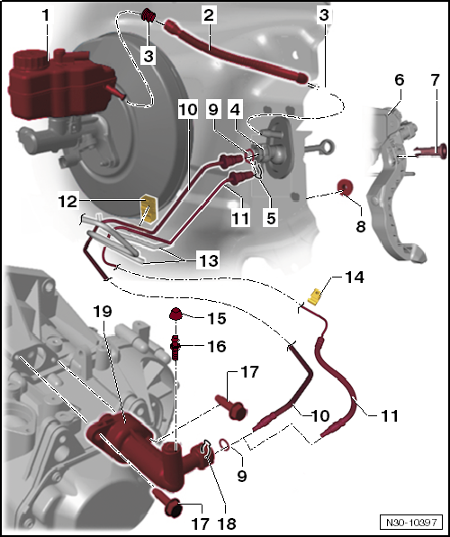
- Brake fluid reservoir
- compensating hose
- Gasket
- Seals and compensation hose are a replacement part
- The seals must be located in the compensation hose.
- Clutch master cylinder
- Remove and install
- Clip
- To remove the pipe or pipe-and-hose line, pull clip out to stop
- Bearing bracket with clutch pedal
- Bearing pin
- for plunger/clutch master cylinder
- Hex nut
- Sealing ring / O-ring
- Slide onto line connection
- Insert with brake fluid
- Sealing rings / O-rings matched to the material of the line connection
- Assignment → Electronic Parts Catalog (ETKA)
- Pipe line
- Installed on left-hand drive vehicles as an alternative to the pipe-and-hose line
- Different length for left-hand drive and right-hand drive
- Assignment → Electronic Parts Catalog (ETKA)
- Pipe-and-hose line
- Bracket
- Left-hand drive only
- Secured to body
- For brake lines, pipe line or pipe-and-hose line
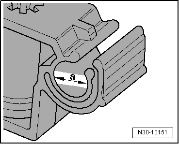
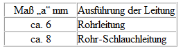
- Identification of brackets for pipe line or pipe-and-hose line
- Brake lines
- Different number
- Assignment → Electronic Parts Catalog (ETKA)
- Bracket
- Right-hand drive only
- Secured to body
- Dust cap
- Bleed valve
- 4,5 N·m
- Bleed clutch hydraulics
- Hex bolt
- Clip
- To remove the pipe line, pull clip out to stop
- Clutch slave cylinder
- Assignment → Electronic Parts Catalog (ETKA)
- Remove and install
Sealing rings / O-rings for pipe-and-hose lines
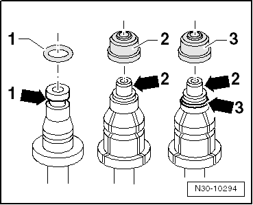
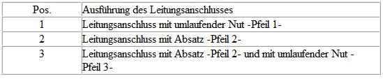
- For line connection with circumferential groove -arrow 1- and -arrow 3-, the sealing ring / O-ring must be installed there.
Left-hand drive, identification of brackets for pipe line or pipe-and-hose line
Assembly overview - clutch release
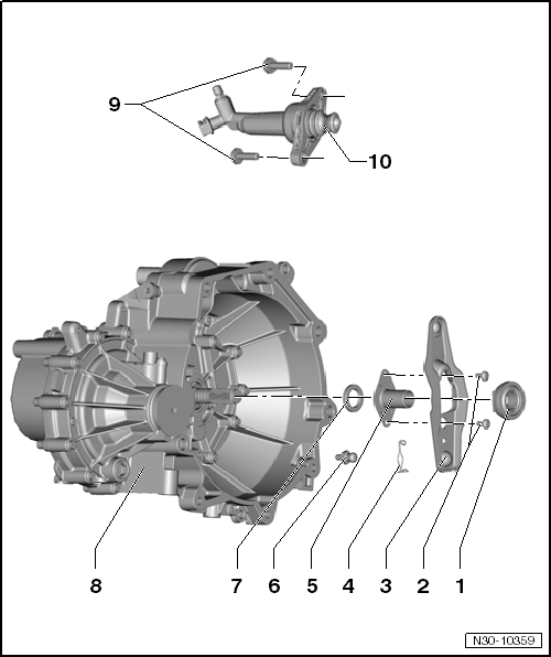
- Release bearing
- To remove and install, remove transmission
- Remove and install together with clutch release lever and guide sleeve, up to
- Do not wash out bearing, only wipe clean
- Replace noisy bearings
- Bolt
- replace after removal
- 5 N·m and continue turning 90º
- Clutch release lever
- To remove and install, remove transmission
- Remove and install together with release bearing and guide sleeve
- Remove old grease
- Retaining spring
- To remove and install, remove transmission
- Secure to clutch release lever
- Guide sleeve
- To remove and install, remove transmission
- Remove and install together with release bearing and clutch release lever, up to
- ball stud
- To remove and install, remove transmission
- Remove old grease
- Grease contact point on ball stud with grease -G 000 100-
- 20 N·m
- Sealing ring for driveshaft
- Replace
- Transmission
- Hex bolt
- 20 N·m
- Clutch slave cylinder
- Remove and install
Remove and install bushing
Removing
Disconnect negative battery cable → Electrical System.
Polo
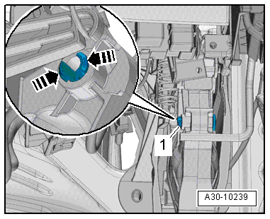
- Remove over-center spring/tension spring
- Press latches together -arrows-, pull pin -1- off to the right.
- Pull clutch pedal into passenger compartment up to stop.
up!
- Press latches of bearing pin for clutch master cylinder pushrod on clutch pedal together. Pull pin off to the left.
- Observe tension spring.
- Pull clutch pedal into passenger compartment up to stop, remove clutch pedal switch -F36- if necessary
Continuation for all
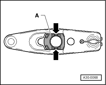
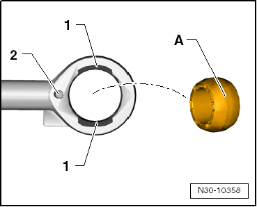
- Turn pushrod of clutch master cylinder so that cutouts -1- or marking -2- are visible.
Cutouts -1- and marking -2- point in the same direction.
- Remove bushing -A- from cutouts -1-.
Installing
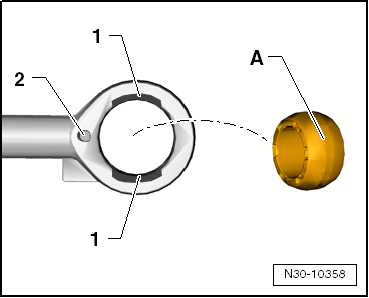
- Turn pushrod of clutch master cylinder so that cutouts -1- or marking -2- are visible.
Cutouts -1- and marking -2- point in the same direction.
- Insert bushing -A- into cutouts -1- and swing into place.
Polo
- Install over-center spring/tension spring
Continuation for all
- Connect pushrod/clutch master cylinder to clutch pedal
- Use new bearing pin.
up!
- Observe tension spring.
- Install clutch pedal switch -F36- if removed
Continuation for all
- Connect battery → Electrical System.
Remove and install clutch pedal
Remove and install clutch pedal, up!
The clutch pedal is removed and installed together with the bearing bracket.
The clutch pedal is not removed from the bearing bracket.
Remove and install tension spring
Remove and install tension spring, up!
Required Special Tools, Test and Measuring Equipment and Auxiliary Items
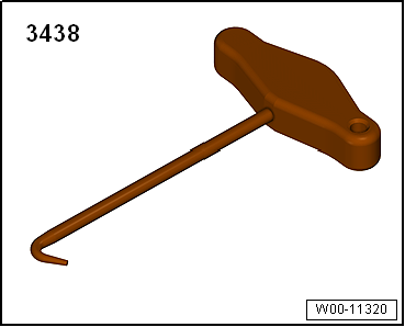
- Hook -3438-
Removing
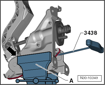
- Remove bearing bracket.
- Clamp bearing bracket carefully in vise -A-.
- A recess in the front area of the bearing bracket -arrow 1- locks onto the vise.
- This prevents the bearing bracket from being pulled out of the vise when removing the tension spring.
- Pull tension spring firmly out of mount and remove.
Installing
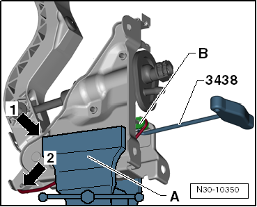
- Remove bearing bracket.
- Clamp bearing bracket carefully in vise -A-.
- A recess in the front area of the bearing bracket -arrow 1- locks onto the vise.
- This prevents the bearing bracket from being pulled out of the vise when installing the tension spring.
- Install new mount -B- for tension spring.
- Lightly grease the following areas for the tension spring:
- Mount -B-
- Mount on clutch pedal -arrow 2-
- Grease → Electronic Parts Catalogue (ETKA)
- Hook tension spring into mount on clutch pedal -arrow 2-.
- Hook tension spring into mount -B- on bearing bracket.
Remove and install bearing bracket
Removing and installing bearing bracket, up!
Required Special Tools, Test and Measuring Equipment and Auxiliary Items
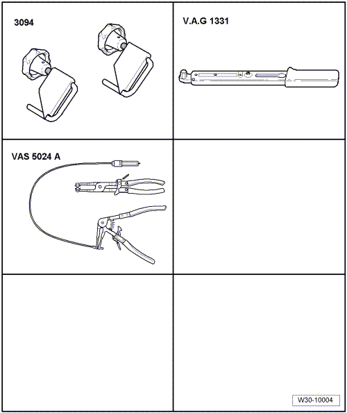
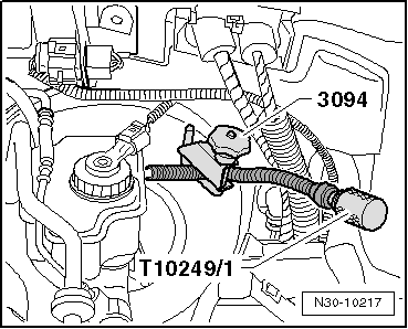
- Hose clamp -3094-
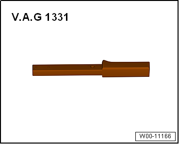
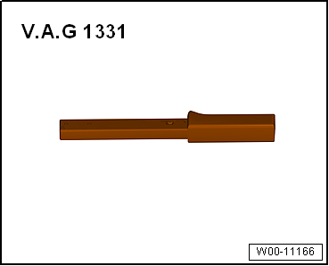
- Torque Wrench -V.A.G 1331-
- Not required, installation tool for spring band clamps -VAS 5024 A-
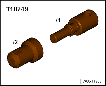
Sealing plug tool -T10249-
Removing
- Remove battery and battery carrier → Electrical system.
- Clamp off the compensating hose to the clutch master cylinder with hose clamp -3094-.

Caution!
Risk of brake fluid leaking out.
- When carrying out the following work, make sure no brake fluid gets onto the side member or onto the transmission. If it does, clean the area thoroughly.
- Place a lint-free cloth under the clutch master cylinder.
- When working in the footwell, protect the floor carpet from leaking brake fluid with a cloth.
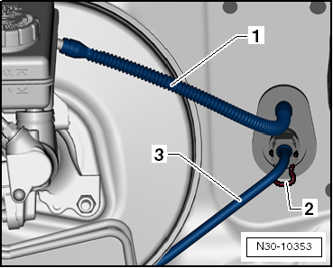
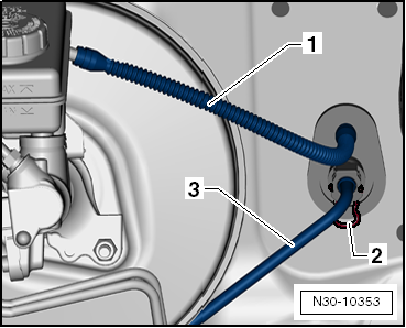
- Pull compensating hose -1- off the clutch master cylinder.
- In addition to clamping, the hose can be sealed with sealing tool -T10249/1- (⇒ previous illustration).
- Pull retaining clip -2- out as far as it will go using a screwdriver or pointed object, and pull pipe -3- off the clutch master cylinder.
- Remove driver footwell cover → Body Assembly Work Interior.
Vehicles with clutch pedal switch -F36-
- Remove clutch pedal switch -F36-.
Left-hand drive
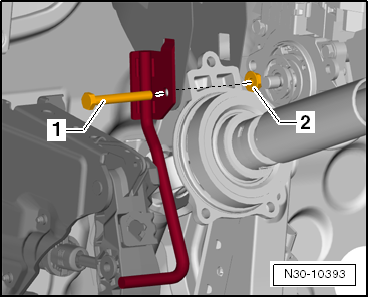
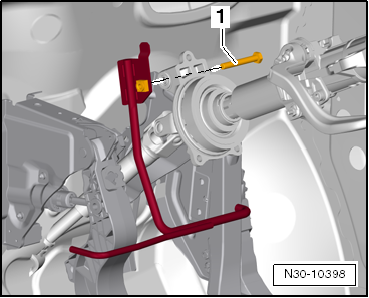
- Remove crash strut; bolt -1-.
Note nut -2-.
Right-hand drive
- Remove crash strut; bolt -1-.
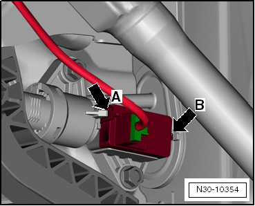
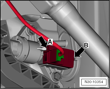
Vehicles with clutch position sensor -G476-:
- Unclip clutch position sensor -G476- from clutch master cylinder -arrow A- and remove from bracket -arrow B-.
- Remove clutch position sensor -G476- with electrical connector attached.
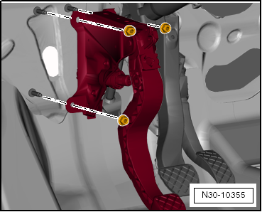
Continuation for all
- Unscrew mounting nuts.
- Remove bearing bracket.
Installing
Installation is in reverse order, observing the following:

Note
Replace self-locking nuts.
- Tighten mounting nuts for bearing bracket.
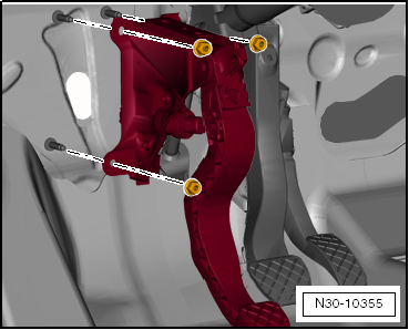
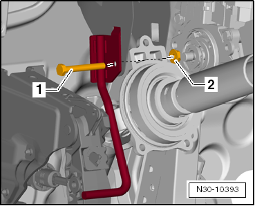
Left-hand drive
- Install crash strut; tighten bolt -1-.
Note nut -2-.
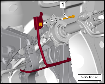
Right-hand drive
- Install crash strut; tighten bolt -1-.
Vehicles with clutch position sensor -G476-:
- Insert clutch position sensor -G476- into bracket on clutch master cylinder -arrow B- and clip in -arrow A-.
- To check, pull on clutch position sensor -G476-.
Vehicles with clutch pedal switch -F36-
- Install clutch pedal switch -F36-.
Continuation for all
- Install driver footwell cover → Body Assembly Work Interior.
- After removing hose clamp -3094-, compensating hose -1- may need to be restored to its original shape.
- Press pipe -3- onto the connection of the clutch master cylinder as far as it will go, and press retaining clip -2- in as far as it will go.
- To check, pull on the line.
- Bleed clutch actuation.
Tightening torques
- Bearing bracket on bulkhead
- Crash strut on steering column
Removing and installing clutch master cylinder
Removing and installing clutch master cylinder, up!
Required Special Tools, Test and Measuring Equipment and Auxiliary Items
- Torque Wrench -V.A.G 1331-
Removing
Remove bearing bracket with clutch master cylinder.
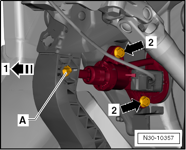
The bearing bracket with clutch master cylinder is shown installed here.
- Pull bearing pin -A- for pushrod/clutch master cylinder out of clutch pedal -direction of arrow 1-.
- Unscrew clutch master cylinder from bearing bracket -arrows 2-.
- Remove clutch master cylinder from bearing bracket.
Installing
Installation is in reverse order, observing the following:
- Replace bearing pin -A- (⇒ illustration above) after removal.
- Bearing pin -A- must audibly engage in clutch pedal.
- To check, carefully pull on bearing pin.
- Screw clutch master cylinder to bearing bracket -arrows 2- (⇒ illustration above).
Tightening torque.
Install bearing bracket with clutch master cylinder.
Tightening torques
- Clutch master cylinder on bearing bracket
Removing and installing clutch slave cylinder
Required Special Tools, Test and Measuring Equipment and Auxiliary Items
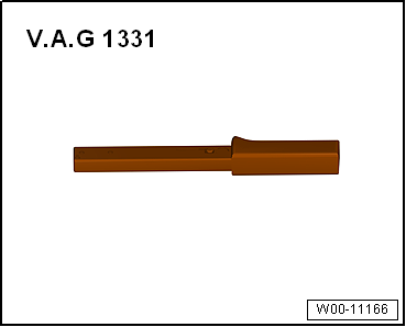
- Torque Wrench -V.A.G 1331-
Removing

Note
- Before replacing the clutch slave cylinder due to a suspected fault, you must first carry out Guided Fault Finding → Vehicle Diagnostic Tester.
- If the clutch slave cylinder is removed with the pipe/hose line still connected to the transmission, do not operate the clutch pedal. Otherwise the piston will be pushed out of the clutch slave cylinder and destroyed.
- If the clutch slave cylinder is not accessible through the air filter, the air filter must be removed.
- Remove battery and battery carrier → Electrical system.
- Remove starter motor → Electrical system.
- Detach gear shift cable, selector cable and cable bracket from transmission and tie up.
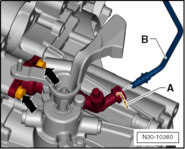
- Place a lint-free cloth under the clutch slave cylinder.
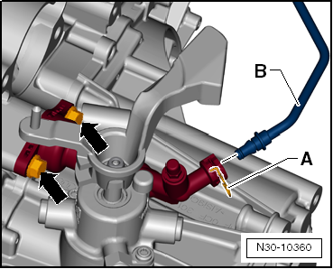
- Release clip -A- with a screwdriver and pull pipe/hose line -B- off the connection.
- Pull pipe/hose line -B- out of the clutch slave cylinder and seal the openings.
- Unscrew bolts -arrows- and remove clutch slave cylinder.
Installing
Installation is in reverse order, observing the following:
- Screw clutch slave cylinder to transmission -arrows-.
- Insert pipe/hose line -B- into clutch slave cylinder as far as it will go.
- Press clip -A- in as far as it will go.
- To check, pull on the line.
- Bleed clutch actuation.
- Install gear shift cable, selector cable and cable bracket.
- Adjust gear shift linkage.
- Install starter motor → Electrical System.
- Install battery → Electrical System.
- If the air filter was removed, install it again now.
Tightening torques
- Clutch slave cylinder on transmission
Removing and installing clutch actuation lines
Required Special Tools, Test and Measuring Equipment and Auxiliary Items
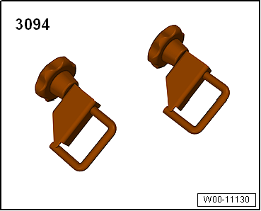
- Hose clamps up to 25 mm -3094-
Removing
- Remove the complete air filter housing if this is needed to access the clutch actuation lines.
- Remove battery and battery carrier → Electrical system.
Polo, left-hand drive
- Unclip engine control module with electrical connector attached from bracket on bulkhead and set aside.
Right-hand drive
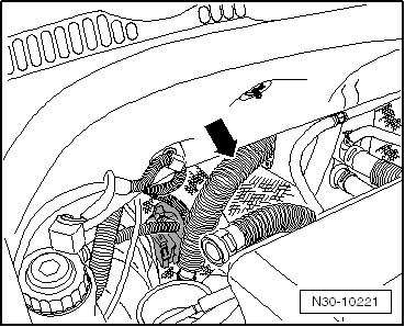
On some vehicles the master cylinder is located behind an air conditioning line -arrow-.
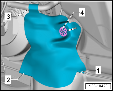
Some engines have a heat shield mat installed. The appearance may differ from the illustration.
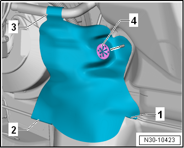
- Remove the heat shield mat. Observe items -1..4-.
Continuation for all

Caution!
Risk of brake fluid leaking out.
- When carrying out the following work, make sure no brake fluid gets onto the side member or onto the transmission. If it does, clean the area thoroughly.
- Place a lint-free cloth under the clutch master cylinder.
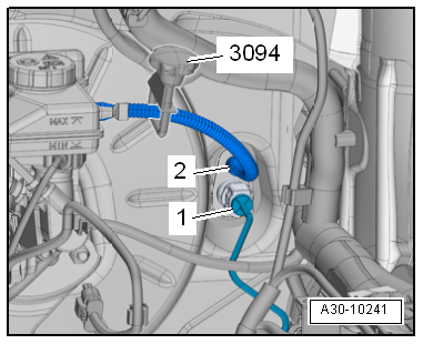
- Clamp off compensating hose -2- to the clutch master cylinder with hose clamp -3094-.

Note
- Clamping the compensating hose with hose clamp -3094- causes permanent deformation.
- However, this does not mean the compensating hose is defective.
- After removing hose clamp -3094-, the compensating hose must be restored to its original shape.
- Pull clip for pipe/hose line -1- out as far as it will go and pull off the pipe/hose line.
- Seal openings.
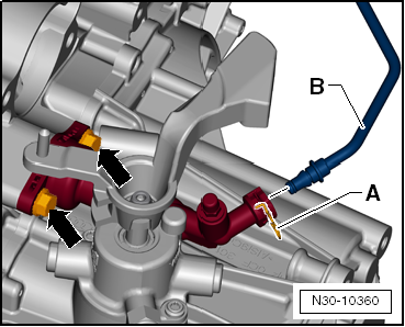
- Pull clip -A- out as far as it will go and pull off pipe/hose line -B-.
- Seal openings.

Note
Disregard the -arrows-.
- Seal open lines and connections as needed with clean plugs from the blanking plug set for engine -VAS 6122-.
- Expose and remove the pipe/hose line.
Installing
Installation is carried out in the reverse order, observing the following:
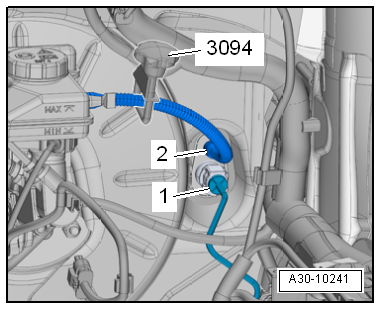
- Connect pipe/hose line -1- to the connection on the master cylinder and the slave cylinder.
- To check, pull on the line.
- After removing hose clamp -3094-, the follow-up hose -2- must be returned to its original shape.
Polo, left-hand drive
- Clip the engine control module, with the electrical connector attached, into the bracket on the bulkhead.
Polo, right-hand drive
- If fitted, tie the heat shield mat around the lines in the sequence -1, 2, 3-.
- Secure the heat shield mat with clamping washer -4-.
Continuation for all
- Bleed clutch actuation.
- Install the battery tray and battery → Electrical System.
- Install the complete air filter housing.
Bleed clutch hydraulics
Required Special Tools, Test and Measuring Equipment and Auxiliary Items
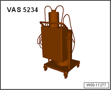
- Brake filling and bleeding unit -VAS 5234-

Note
- After working on the hydraulics, the clutch actuation must be bled.
- During the following work, make sure no brake fluid gets onto the side member or the transmission.
- Pre-filling the system is not necessary!
- Before bleeding, fill the brake fluid reservoir with brake fluid up to the "Max" mark.
- The clutch pedal is in its rest position and is not depressed.
- Brake fluid: assignment → Electronic Parts Catalogue (ETKA).
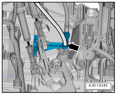
- Remove the complete air filter housing if this is needed to access the bleeder valve (-arrow-, figure below).
Polo
- Remove the protective cap from the bleeder valve -arrow-.
up!
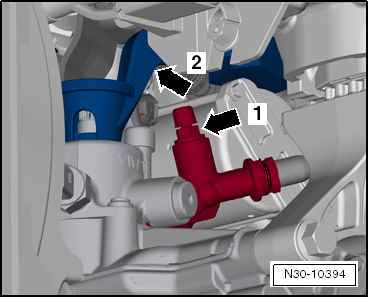
- Raise the vehicle.
The clutch slave cylinder -arrow 1- is accessible from the left, underneath the vehicle, near the gear selector lever -arrow 2-.
Continuation for all
- Remove the protective cap from the bleeder valve -arrow-.
- Connect the brake filling and bleeding unit.
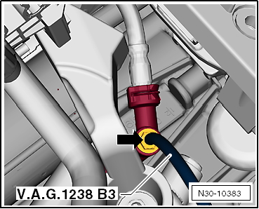
For bleeding, use the bleeder hose (670 mm long) -V.A.G 1238/B3- if necessary.
- Then connect the bleeder hose to the collecting bottle of the brake bleeding unit.
- Push the bleeder hose onto the bleeder valve -arrow- (shown here from above).
- Switch on the brake filling and bleeding unit.
- Working pressure 2.0 bar gauge pressure.
- Open the bleeder valve.
- Let approx. 100 cm3 of brake fluid flow out.
- Close the bleeder valve.
- Briskly depress the clutch pedal from stop to stop 10 to 15 times.
- Open the bleeder valve.
- Let a further 50 cm3 of brake fluid flow out.
- Close the bleeder valve.
- Switch off the brake filling and bleeding unit and fully release the pressure on the unit.
- After completing the bleeding procedure, depress the clutch pedal several times.
Tightening torque:
- Bleed valve
Remove and install clutch pedal switch -F36-
To ensure a secure fit in the clutch pedal bracket, clutch pedal switch -F36- must only be installed once.
Removing
- Remove driver footwell cover → Body Assembly Work Interior.
- Pull the connector off clutch pedal switch -F36-.
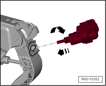
- Turn clutch pedal switch -F36- 45° in the -arrow direction- on the bracket and pull it out of the holder.
Installing
- Grease the plunger.
- Assign the grease via the Electronic Parts Catalogue (ETKA).
Clutch pedal switch -F36- is installed from the passenger compartment.
- When installing clutch pedal switch -F36-, the clutch pedal must always remain in the rest position. During the entire installation, the clutch pedal may only be touched by the plunger head of clutch pedal switch -F36-.
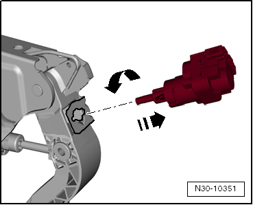
- Insert clutch pedal switch -F36- into the holder of the bracket and turn it 45° in the -arrow direction-.
- Connect the connector for clutch pedal switch -F36-.
- Install driver footwell cover → Body Assembly Work Interior.
Check clutch master and slave cylinders
Before replacing the clutch master cylinder due to a suspected fault, first perform guided fault finding with the vehicle diagnostic tester.
Remove and install clutch position sensor -G476-
Remove and install clutch position sensor -G476-, up!
Removing
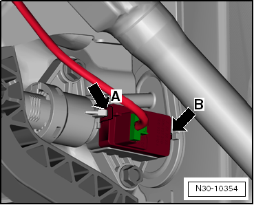
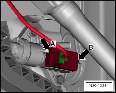
- Unclip clutch position sensor -G476- from clutch master cylinder -arrow A- and remove from bracket -arrow B-.
- Remove clutch position sensor -G476- from the slave cylinder and disconnect the electrical connector.
Installing
- Insert clutch position sensor -G476- into bracket on clutch master cylinder -arrow B- and clip in -arrow A-.
- To check, pull on clutch position sensor -G476-.
- Connect the electrical connector.
Repairing the clutch release
Required Special Tools, Test and Measuring Equipment and Auxiliary Items
- Torque Wrench -V.A.G 1331-
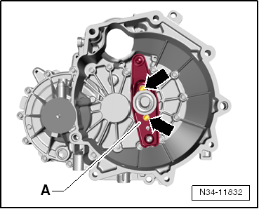
Remove and install clutch release lever -A- with release bearing and guide sleeve
- The transmission has been removed.
- Unscrew bolts -arrows-.
- Pull the clutch release lever with release bearing and guide sleeve off the input shaft and ball stud.
Install in reverse order.
- Install the transmission.
Tightening torques
- Guide sleeve on transmission
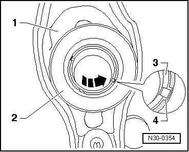
Remove and install guide sleeve from release bearing
- Remove the clutch release lever with release bearing and guide sleeve.
- Push guide sleeve -3- upward out of release bearing -2-.
- Turn guide sleeve -3- approx. 90° in the arrow direction relative to release bearing -2- until the locking lugs of the guide sleeve align with the grooves -4- of the release bearing.
- In this position, pull the guide sleeve out of the release bearing.
Install in reverse order.
- Install the clutch release lever with release bearing and guide sleeve.
Remove and install release bearing
- Remove the clutch release lever with release bearing and guide sleeve.
- Squeeze the locking lugs -arrows- on the back of the clutch release lever together and remove release bearing -A- from the clutch release lever.
- To install, press release bearing -A- into the clutch release lever until the locking lugs -arrows- engage.
- Grease the contact point of the clutch release lever on the ball stud with grease -G 000 100-.
- Install the clutch release lever with release bearing and guide sleeve.