Cylinder head
Assembly overview - cylinder head
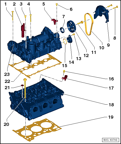
- Bolt
- replace after removal
- Observe tightening sequence "Removing and installing camshaft housing"
- 10 N·m +180º
- Valve 1 for camshaft adjustment -N205-
- Bolt
- 8 N·m
- Bolt
- replace after removal
- Observe tightening sequence "Removing and installing camshaft housing"
- 10 N·m +180º
- Hall sender -G40-
- Bolt
- 8 N·m
- Sealing ring
- Removing and installing "Removing and installing camshaft seal, exhaust camshaft, transmission side"
- Bolt
- 8 N·m
- Timing belt cover
- V-ribbed belt
- for coolant pump
- replace after removal
- Bolt
- 20 N·m
- Timing belt sprocket
- for coolant pump drive
- Bolt
- 8 N·m
- Filler Cap
- O-ring
- Replace if damaged
- Bolt
- 8 N·m
- Coolant temperature sender -G62-
- Cylinder head
- Removing and installing "Removing and installing cylinder head"
- Reworking of valve seats is not permitted
- Re-machining cylinder head surface on cylinder block side "Checking camshaft axial clearance"
- Gasket
- replace after removal
- Cylinder head bolt
- replace after removal
- Observe assembly instructions and sequence when loosening and tightening ""Cylinder head - tightening torque and sequence""
- Oil strainer
- replace after removal
- inserted into the cylinder head

Note
- Depending on production date, variants with and without oil strainer are used.
- If no strainer is fitted at the factory, a strainer is integrated in camshaft adjustment valve 1 -N205- as a replacement.
- If the strainer is fitted twice, damage may occur!
- Gasket
- replace after removal
- Camshaft housing
- Removing and installing "Removing and installing camshaft housing"

Note
- The camshafts cannot be removed.
- In case of repair, the camshaft housing can only be replaced complete with the camshafts.
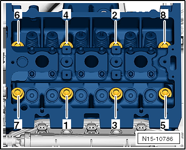
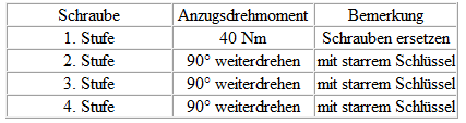
Cylinder head - tightening torque and sequence
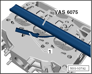
Checking cylinder head for distortion
Check with 500 mm straightedge -VAS 6075- and feeler gauge -1-.
Max. permissible distortion: 0.05 mm
Removing and installing cylinder head
- From production date week 22 of 2012, a modified timing belt tensioner pulley is fitted.
- With the modified tensioner pulley, the engine no longer needs to be supported with the engine support fixture when removing the cylinder head.
Required Special Tools, Test and Measuring Equipment and Auxiliary Items
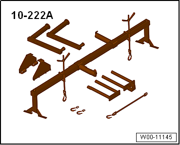
- Engine support fixture -10-222 A-
- Adapter -10-222 A/31-2- (not illustrated)
- Support -10-222 A/31-3- (not illustrated)
- Adapter -10-222 A/31-5- (not illustrated)
- Shackle -10-222 A/12- (not illustrated)
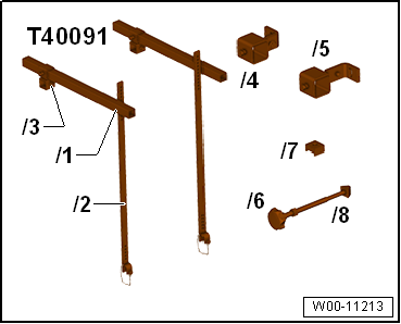
- Engine support fixture basic set -T40091-
- Square tube -T40091/1- (not illustrated)
- Connector -T40091/3- (not illustrated)
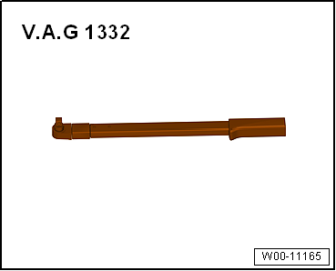
- Torque Wrench -V.A.G 1332-
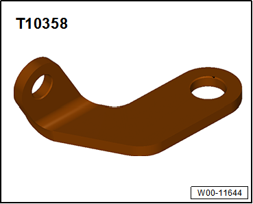
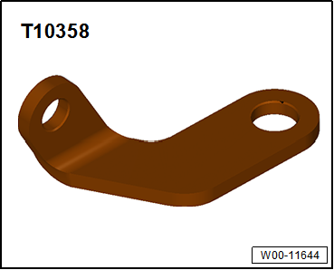
- Holder -T10358-
- The engine must be at most hand-warm.
Removing
- Remove camshaft housing "Removing and installing camshaft housing".
- Unscrew fastening bolts -1-.
- Unscrew fastening bolt on catalytic converter and remove bracket -2-.
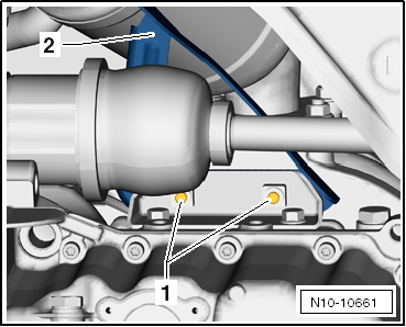
- Unscrew fastening nuts -arrows- and pull catalytic converter off the studs.
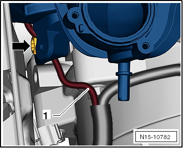
- Unscrew mounting bolt of intake manifold bracket -arrow-.

- Unclip wiring harness -1- from below intake manifold.
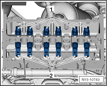
- Remove roller rocker arms -1- and -2- and place them on a clean surface.
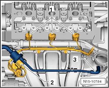
- Disconnect connectors -1- of fuel injectors.
- Disconnect connector -2- from solenoid valve 1 for charcoal canister -N80-.
- Also disconnect connectors -arrows- from oil pressure switch and on intake manifold.
- Disconnect hose -3- from intake manifold and unclip line from solenoid valve 1 for charcoal canister -N80-.
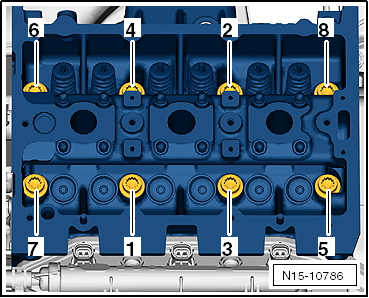
- Loosen and unscrew cylinder head bolts in the specified sequence -1- to -8-.
- Carefully lift off cylinder head together with intake manifold.
- Remove cylinder head gasket.
Installing
Risk of damage to sealing surfaces. Carefully remove gasket residue from cylinder head and cylinder block. Make sure no long scratches or grooves are created. Risk of damage to cylinder block. Blind holes for cylinder head bolts in cylinder block must not contain oil or coolant. Risk of leakage at cylinder head gasket. Carefully remove abrasive and grinding residue. Only take new cylinder head gasket out of packaging immediately before installation. To prevent damage to the silicone coating and bead area of the cylinder head gasket, handle gasket extremely carefully.
- Set piston of 1st cylinder to top dead center and turn crankshaft back slightly.

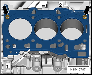
- Place new cylinder head gasket -1- onto centering sleeves -arrows-. The marking (part number) -2- must be legible.
- Place cylinder head on, insert the 8 new cylinder head bolts and tighten by hand.
- Tighten cylinder head bolts in the sequence shown -1- to -8- as follows "Cylinder head - tightening torque and sequence".

Note
- Risk of damage to valves and piston crowns.
- When turning the camshaft, the crankshaft must not be at TDC.
- Install camshaft housing "Removing and installing camshaft housing".
- Set valve timing "Setting valve timing".
- Install coolant pump "Removing and installing coolant pump".
- Change engine oil.
- Change coolant "Draining and filling coolant".
Reassembly is carried out in the reverse order of removal.
Tightening torques
- "Assembly overview - Cylinder head"
- "Assembly overview - Exhaust emission control"
- "Assembly overview - Coolant pump"
- "Assembly overview - Intake manifold"
Removing and installing camshaft housing

Note
- The camshafts cannot be removed.
- In case of repair, the camshaft housing can only be replaced complete with the camshafts.
Required Special Tools, Test and Measuring Equipment and Auxiliary Items
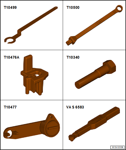
- Key -T10499-
- Insert tool -T10500-
- Installation tool -T10476A-
- Locking bolt -T10340-
- Camshaft locking tool -T10477-
- Torque wrench -VAS 6583-
- Counterhold tool -T10172A-
- Engine support fixture -10-222 A-
- Adapter -10-222 A/31-2- (not illustrated)
- Support -10-222 A/31-3- (not illustrated)
- Adapter -10-222 A/31-5- (not illustrated)
- Shackle -10-222 A/12- (not illustrated)
- Engine support fixture basic set -T40091-
- Square tube -T40091/1- (not illustrated)
- Connector -T40091/3- (not illustrated)
- Holder -T10358-
Removing
- Disconnect battery ground strap with ignition switched off.
- Remove air filter housing “Removing and installing air filter housing”.
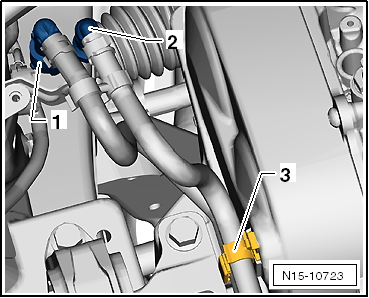
- Unlock and disconnect fuel supply line -1- and vent line -2-.
- Open cable routing -3- and remove hoses.
- Plug lines so that no dirt can enter the fuel system.
- Unhook clips -arrow-.
- Unscrew mounting bolt -1- and remove cover -2-.
- Unscrew mounting bolts -arrows-.
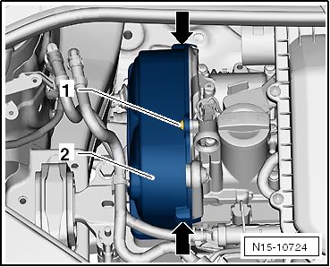
- Unclip line routing from cover.
- Remove cover -1- and cap -2-.
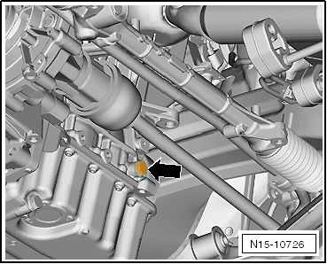
Vehicles without marking on crankshaft

- Unscrew sealing plug -arrow- from crankcase.
- Lower lift platform fully.

Note
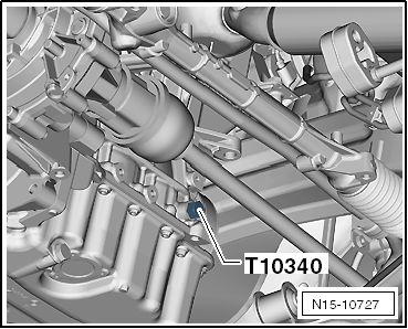
- The lift platform must be lowered fully so that locking bolt -T10340- can be screwed into the crankcase.
- With vehicle raised, the drive shaft is in front of the bore.
- Screw locking bolt -T10340- into crankcase from above as far as it will go.
If locking bolt -T10340- cannot be screwed in as far as it will go, the crankshaft is not in the correct position!
In this case, proceed as described below.
- Unscrew locking bolt.
- Turn crankshaft 90° in direction of engine rotation.
- Turn locking bolt -T10340- into crankcase as far as it will go.
- Tighten locking bolt -T10340- with 30 N·m.
- Turn crankshaft in direction of engine rotation as far as it will go.
The locking bolt -T10340- blocks the crankshaft in the direction of engine rotation.
Continuation for all vehicles
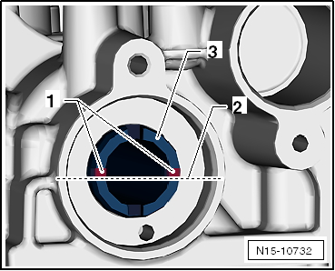
- The slots -1- of the intake camshaft -3- are above the camshaft centerline -2-.
- The slots -1- of the exhaust camshaft are above the camshaft centerline -2-.
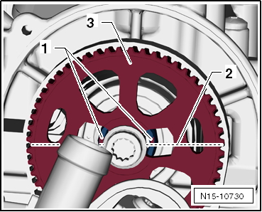
- The cutouts of the gear -3- point slightly upward in the area of the slots.
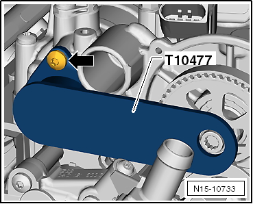
- The camshaft locking tool -T10477- must fit in easily.
- Do not use a impact tool to install the camshaft locking tool!
- Insert camshaft locking tool -T10477- into the camshafts as far as it will go and tighten the bolt -arrow- by hand.
- Drain coolant “Draining and refilling coolant”.
- Remove coolant pump, refer to "Removing and installing coolant pump".

Note
The coolant pump timing belt pulley on the camshaft is not removed.
- Remove throttle valve control unit -J338-, refer to "Removing and installing throttle valve control unit -J338-".
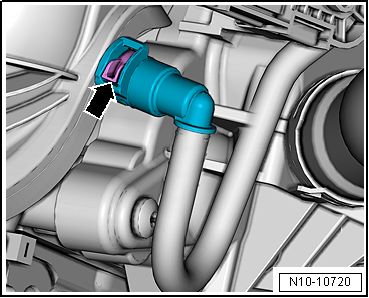
- Open the latch of the vacuum hose -arrow- on the intake manifold and disconnect the vacuum hose.

Note
From calendar week 22 of 2012 a modified timing belt tensioner roller is fitted. Removing and installing the engine mount, the engine mount bracket and the lower timing belt cover is not required.
Procedure for vehicles up to production date calendar week 22 of 2012
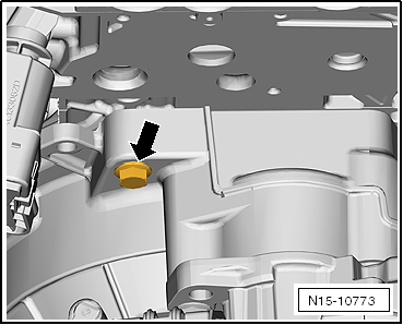
- Unscrew transmission mounting bolt -arrow-.
- Bolt holder -T10358- to the transmission using the mounting bolt.
- Remove and install poly-V belt, refer to "Removing and installing poly-V belt".
- Remove windshield wiper arms, refer to Electrical System.
- Remove cowl panel cover, refer to Body Assembly Work Exterior.
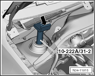
- Fit adapters -10-222A/31-2- onto the strut assemblies.
- The brackets of the adapters -arrow- point toward the engine compartment.
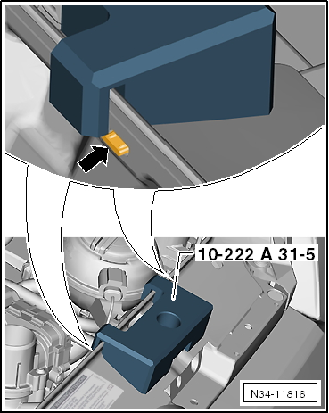
- Place the mount -10-222A/31-5- over the hood latch.
- The position is between 2 ribs -arrow-.
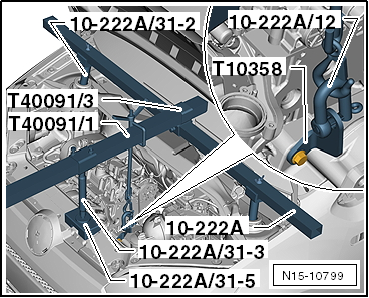
- Fit the safety device -10-222 A- and engine safety device basic -T40091- with the adapters as shown.
- Bolt shackle -10-222 A/12- to holder -T10358-.
- Hook the spindle onto the shackle and relieve the engine mount slightly by turning the spindle.
- Unscrew earth strap -1-.
Unscrew fastening bolts -arrows- and remove the engine-side unit mount.
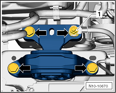
- Unscrew mounting bolt -1- and swing the alternator in the -arrow direction-.
- Raise the engine by turning the spindle far enough that the mounting bolt of the engine mount bracket can be unscrewed.

- Unscrew the mounting bolts -2- of the engine mount bracket and the 3 bolts -1- of the lower timing belt cover.
- Pull the engine mount bracket out upward.
Further procedure for all vehicles
Risk of damaging the camshaft through incorrect handling. Never use the camshaft locking tool as a counterhold.

- Unscrew sealing bolt -1- on the intake side camshaft gear, using counterhold -T10172- with adapter -T10172/1-.

Note
When adjusting the valve timing, both camshaft gears must be loose.
- Hold the camshaft adjuster and camshaft gear with counterhold -T10172A-.

- Loosen mounting bolts -1- and -2-.
- Loosen the tensioner roller mounting bolt and release the tensioner roller, refer to "Removing and installing timing belt".
- Slide the timing belt off the camshaft gears.

- Unscrew mounting bolts -1- and -2- and remove the camshaft gears.

Note
The mounting bolts -1- and -2- must be replaced.

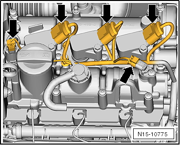
- Disconnect connectors -arrows- and unclip the wiring harness from the camshaft housing.
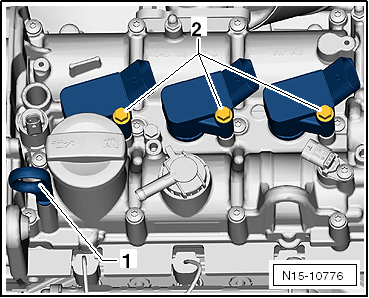
- Pull out oil dipstick -1- and unscrew mounting bolts -2- of the ignition coils with output stages.
- Pull the ignition coils with output stages off the spark plugs.
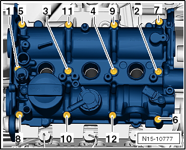
- Loosen and unscrew the camshaft housing mounting bolts in the specified sequence -1- to -12-.
- Lift the camshaft housing vertically off the cylinder head.
- Remove the gasket.
- Clean the sealing surfaces. They must be free of oil and grease.
Installing
Requirement
The pistons must not be at top dead center.

Note
When turning the camshafts, the valves can strike pistons located at top dead center.
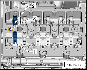
- Check that the roller rocker arms are correctly clipped onto the valve stem ends -1- and the respective support elements -2-.

Note
- Depending on production date, variants with and without oil strainer are used.
- If no strainer is fitted at the factory, a strainer is integrated in camshaft adjustment valve 1 -N205- as a replacement.
- If the strainer is fitted twice, damage may occur!
- Replace sealing ring with oil strainer -3-.
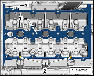
- Place new gasket -1- onto dowel pins -2-.
The part number -3- of the gasket can be read from above.
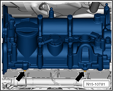
Risk of the roller rocker arms slipping off the valve stem ends and the compensating elements. Lower the camshaft housing vertically from above and slowly onto the cylinder head.
- Carefully place the camshaft housing vertically from above onto the dowel pins -arrows-.
Note the different bolt lengths.
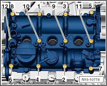
- Tighten new camshaft housing mounting bolts in the specified sequence -1- to -12-.
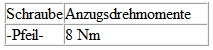
- Tighten the mounting bolt -arrow- of the ground strap.

Vehicles without marking on crankshaft
- Set valve timing "Setting valve timing".
Vehicles with marking on the crankshaft
- Install timing belt, refer to "Removing and installing timing belt, for vehicles with TDC marking on crankshaft".
Continuation for all vehicles
Install coolant pump, refer to "Removing and installing coolant pump".
- Install throttle valve control unit -J338-, refer to "Removing and installing throttle valve control unit -J338-".
- Top up coolant "Draining and topping up coolant".
Reassembly is carried out in the reverse order of removal.
Tightening torques
- "Assembly overview - Unit mounting"
- "Assembly overview - Ignition system"
Checking compression pressure
Required Special Tools, Test and Measuring Equipment and Auxiliary Items
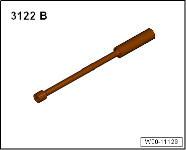
- Spark plug wrench -3122 B-
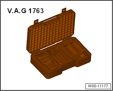
- Compression tester -V.A.G 1763-
- Adapter -VAS 5161A /12-
Test conditions
- The engine oil temperature must be at least 30 ºC.
Test procedure
- Remove air filter housing “Removing and installing air filter housing”.
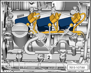
- Disconnect connector -1- from the ignition coils.
- Unscrew mounting bolts -2- and pull the ignition coils off the spark plugs.
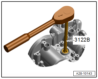
- Remove spark plugs using spark plug wrench -3122 B-.
- Remove the fuse for the fuel injectors. For fuse assignment, refer to Wiring Diagrams, Electrical Fault Finding and Component Locations.
- Screw adapter -VAS 5161A /12- into the spark plug thread and tighten lightly.
- Connect compression tester -V.A.G 1763- to adapter -VAS 5161A /12-.
- Check compression pressure with compression tester -V.A.G 1763-; for operation, refer to the operating instructions.
- Crank the engine until the tester shows no further pressure increase.
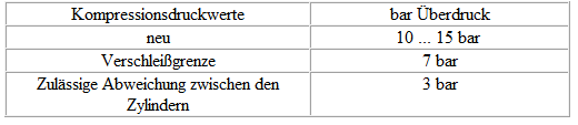
Compression pressure values
Assembly
Installation is carried out in the reverse order, observing the following:
- Install spark plugs.
- Install ignition coils.
- Erase fault memory entries caused by the test, refer to Vehicle Diagnostic Tester, Reading fault memory, then generate readiness code.