Valve train
Assembly overview - Valve train

- Cylinder head
- Removing and installing "Removing and installing cylinder head"
- Re-machining cylinder head surface on cylinder block side "Checking camshaft axial clearance"
- Roller rocker arm
- Check roller bearing for smooth running
- Lightly oil contact surfaces to valves and rollers before installation
- For installation, clip onto support element with the retaining clip
- Support element
- do not mix up
- with hydraulic valve lash adjustment
- Oil running surface
- Valve spring retainer
- Valve spring
- remove and install "Removing and installing valve stem seals"
- Valve collets
- Valve stem seal
- replace "Removing and installing valve stem seals"
- Valves
- do not rework
- lapping in of the valve seat sealing surfaces is permitted
- Lightly oil valve stems and valve ends before installation
Measuring camshaft axial clearance
Required Special Tools, Test and Measuring Equipment and Auxiliary Items
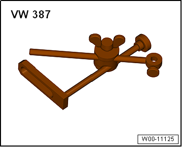
- Universal dial gauge holder -VW 387-
- Dial gauge
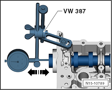
Checking camshaft axial clearance
Carry out measurement with the camshaft housing removed.
- Apply thumb pressure to the camshaft at one of the middle cams and check axial clearance by moving the camshaft back and forth.
Wear limit: max. 0.25 mm
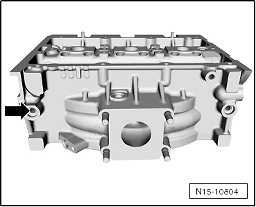
Resurfacing cylinder head sealing surface on cylinder block side
- The dimension reference point is at the center of bore 14H7 -arrow-
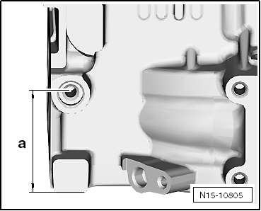
Measured is
Reworking dimension cylinder head: a (center of bore 14H7 to combustion chamber surface of cylinder head) = 58 mm ± 0.1 mm.

Note
If dimension -a- is undercut, resurfacing the cylinder head is not permitted!
Removing and installing camshaft seal
Removing and installing camshaft seal, belt pulley side ► 22.2012
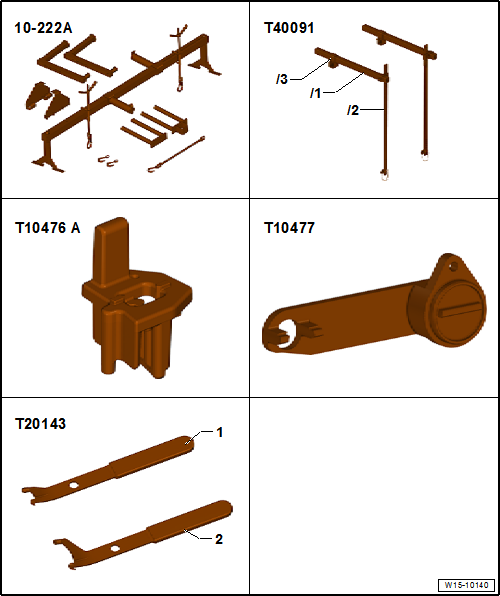
Required Special Tools, Test and Measuring Equipment and Auxiliary Items
- Engine support fixture -10-222 A-
- Engine support fixture basic set -T40091-
- Installation tool -T10476A-
- Camshaft locking tool -T10477-
- Extractor hook -T20143/1-
- Installation device -T10478 B-
- Counterhold tool -T10172A-
Removing
- Remove air filter housing “Removing and installing air filter housing”.

- Unlock and disconnect fuel supply line -1- and vent line -2- → Fuel supply - petrol engines.
- Open cable routing -3- and remove hoses.
- Plug lines so that no dirt can enter the fuel system.
- Unhook clips -arrow-.

- Unscrew mounting bolt -1- and remove cover -2-.
- Unscrew mounting bolts -arrows-.
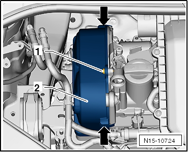
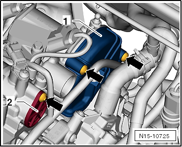
- Unclip line routing from cover.
- Remove cover -1- and cap -2-.
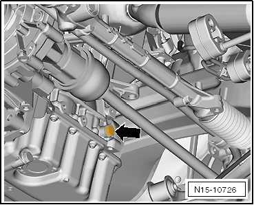
- Unscrew sealing plug -arrow- from crankcase.
- Lower lift platform fully.

Note
- The lift platform must be lowered fully so that locking bolt -T10340- can be screwed into the crankcase.
- With vehicle raised, the drive shaft is in front of the bore.
- Screw locking bolt -T10340- into crankcase from above as far as it will go.
Risk of engine damage. If camshaft locking tool -T10494- cannot be inserted as far as it will go, the crankshaft is not in the correct position. Turn the crankshaft further in the direction of engine rotation -arrow direction- until the "TDC mark" is reached again.
- Unscrew locking bolt.
- Turn crankshaft 90° in direction of engine rotation.
- Turn locking bolt -T10340- into crankcase as far as it will go.
- Tighten locking bolt -T10340- with 30 N·m.
- Turn crankshaft in direction of engine rotation as far as it will go.
The locking bolt -T10340- blocks the crankshaft in the direction of engine rotation.

The marked tooth gap -1- of the camshaft adjuster -3- is opposite web -2- on the camshaft housing.
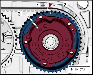
The marked tooth -1- of the exhaust camshaft sprocket -3- is opposite web -2- on the camshaft housing.
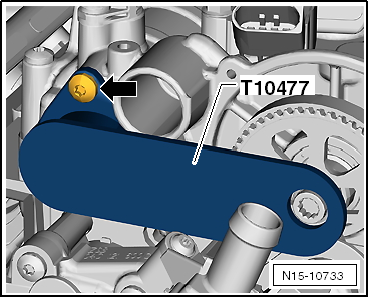
Risk of damage to camshaft. The camshaft locking tool -T10477- must engage easily. Do not insert the camshaft locking tool using an impact tool!

- Insert camshaft locking tool -T10477- into the camshafts as far as it will go and tighten the bolt -arrow- by hand.
- Remove serpentine belt “Removing and installing serpentine belt”.
- Remove windshield wiper arms, refer to Electrical System.
- Remove cowl panel cover, refer to Body Assembly Work Exterior.
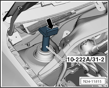
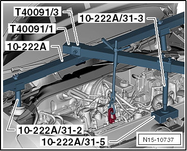
- Fit adapters -10-222A/31-2- onto the strut assemblies.
- Angle of adapter -arrow- points towards engine compartment.
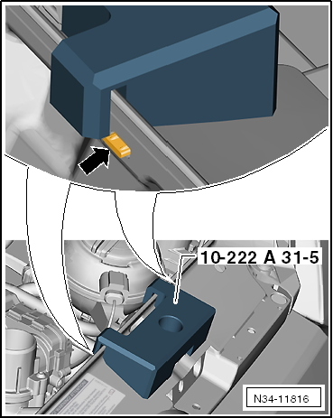
- Place the mount -10-222A/31-5- over the hood latch.
- The position is between 2 ribs -arrow-.
- Fit the safety device -10-222 A- and engine safety device basic -T40091- with the adapters as shown.
- Support engine at right eyelet and slightly relieve engine mount by turning spindle.
- Unscrew earth strap -1-.
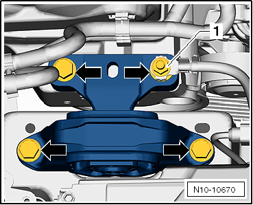
Unscrew fastening bolts -arrows- and remove the engine-side unit mount.
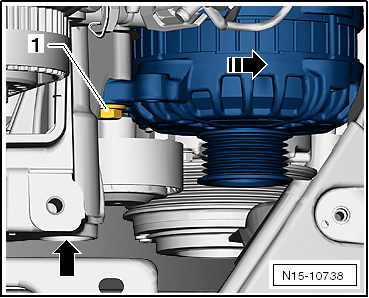
- Unscrew mounting bolt -1- and swing the alternator in the -arrow direction-.
- Raise the engine by turning the spindle far enough that the mounting bolt of the engine mount bracket can be unscrewed.
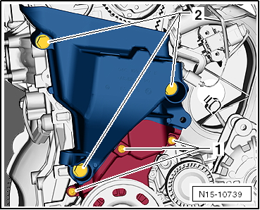
- Unscrew the mounting bolts -2- of the engine mount bracket and the 3 bolts -1- of the lower timing belt cover.
Risk of damage to camshaft. When loosening and tightening the fastening bolts, the camshaft gears must be held with counterhold tool -T10172A-. Camshaft locking tool -T10477- must not be loaded when tightening the camshaft gears.
- Mark direction of rotation of timing belt with a pen.
- Hold camshaft adjuster with counter-holder -T10172A- and unscrew sealing plug -1-.

Note
- When adjusting the valve timing, both camshaft gears must be loose.
- Therefore, if only one seal ring is replaced, both camshaft gears must be loosened.
- Hold the camshaft adjuster and camshaft gear with counterhold -T10172A-.
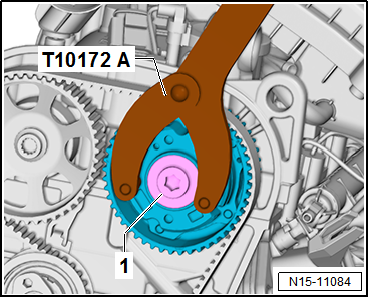
- Loosen mounting bolts -1- and -2-.

Note
- A small amount of oil may escape while removing the camshaft adjuster.
- To prevent engine oil from reaching the timing belt, place a rag underneath before removing the camshaft adjuster!
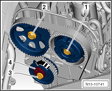
- Loosen tensioner pulley retaining bolt -3- and release tensioner pulley at hexagon socket -4- in the -arrow direction-.
- Slide the timing belt off the camshaft gears.
Risk of damage to timing belt! The timing belt consists of glass fibre cord fabric. The diameter of the timing belt must therefore never be less than 50 mm (approx. Ø of the crankshaft gear). Falling below this value has a negative effect on the service life of the timing belt.
- Unscrew camshaft gear fastening bolts and remove gear.
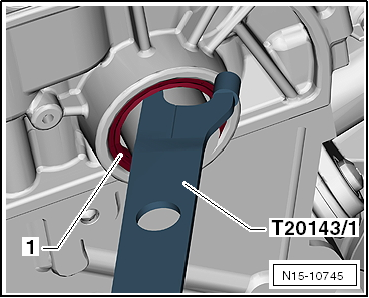
- Pull out seal -1- using extraction hook -T20143/1-.
Installing

Note
Do not oil new seal ring.
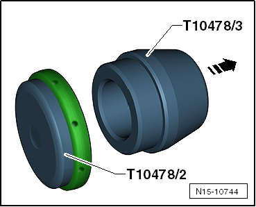
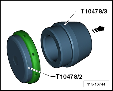
- Join installation sleeves -T10478/2- and -T10478/3- together in the -arrow direction-.
- Slide new seal ring onto installation sleeve -T10478/2- in the -arrow direction-.
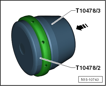
- Pull off installation sleeve -T10478/3- in the -arrow direction-.
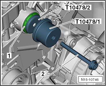
- Place installation sleeve -T10478/2- with seal ring -1- onto the camshaft.
- Draw in pressure piece -T10478/1- with fastening bolt for camshaft adjuster -2- until it stops.

Note
Bolt -T10478/4- is used to install the seal ring on the exhaust camshaft.
- Set valve timing "Setting valve timing".
Risk of engine damage. After completing the work, make sure that locking bolt -T10340- and camshaft locking tool -T10477- have been removed.
Tightening torque, crankcase sealing plug: 30 N·m
Reassembly is carried out in the reverse order of removal.
Removing and installing camshaft seal, belt pulley side 22.2012 ►

Note
From calendar week 22 of 2012, a modified tensioner roller is fitted, which simplifies replacing the camshaft seal.
Required Special Tools, Test and Measuring Equipment and Auxiliary Items
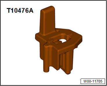
- Installation tool -T10476A-
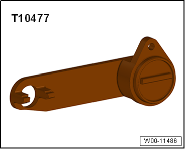
- Camshaft locking tool -T10477-
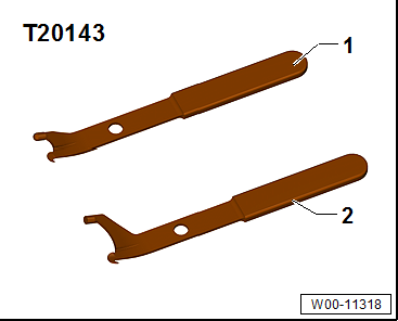
- Extractor hook -T20143/1-
- Installation device -T10478B-

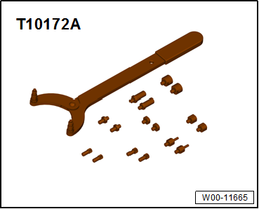
- Counterhold tool -T10172A-
Removing
- Remove air filter housing “Removing and installing air filter housing”.
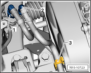
- Unlock and disconnect fuel supply line -1- and vent line -2-.
- Open cable routing -3- and remove hoses.
- Plug lines so that no dirt can enter the fuel system.
- Unhook clips -arrow-.
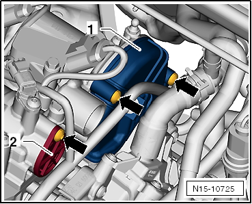
- Unscrew mounting bolt -1- and remove cover -2-.
- Unscrew mounting bolts -arrows-.

- Unclip line routing from cover.
- Remove cover -1- and cap -2-.
- Unscrew sealing plug -arrow- from crankcase.
- Lower lift platform fully.

Note
- The lift platform must be lowered fully so that locking bolt -T10340- can be screwed into the crankcase.
- With vehicle raised, the drive shaft is in front of the bore.

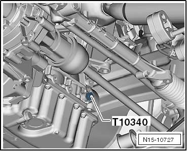
- Screw locking bolt -T10340- into crankcase from above as far as it will go.
- If locking bolt -T10340- cannot be screwed in as far as it will go, the crankshaft is not in the correct position!
- In this case, proceed as described below.
- Unscrew locking bolt.
- Turn crankshaft 90° in direction of engine rotation.
- Turn locking bolt -T10340- into crankcase as far as it will go.
- Tighten locking bolt -T10340- with 30 N·m.
- Turn crankshaft in direction of engine rotation as far as it will go.
The locking bolt -T10340- blocks the crankshaft in the direction of engine rotation.
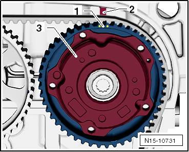
The marked tooth gap -1- of the camshaft adjuster -3- is opposite web -2- on the camshaft housing.
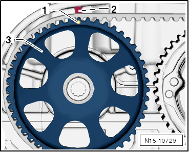
The marked tooth -1- of the exhaust camshaft sprocket -3- is opposite web -2- on the camshaft housing.
Risk of damage to camshaft. The camshaft locking tool -T10477- must engage easily. Do not insert the camshaft locking tool using an impact tool!
- Insert camshaft locking tool -T10477- into the camshafts as far as it will go and tighten the bolt -arrow- by hand.
Risk of damage to camshaft. When loosening and tightening the fastening bolts, the camshaft gears must be held with counterhold tool -T10172A-. Camshaft locking tool -T10477- must not be loaded when tightening the camshaft gears.

- Hold camshaft adjuster with counter-holder -T10172A- and unscrew sealing plug -1-.

Note
- When adjusting the valve timing, both camshaft gears must be loose.
- Therefore, if only one seal ring is replaced, both camshaft gears must be loosened.
- Hold the camshaft adjuster and camshaft gear with counterhold -T10172A-.
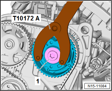
- Loosen mounting bolts -1- and -2-.
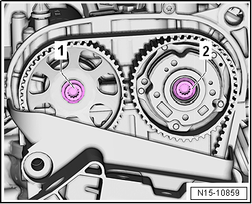
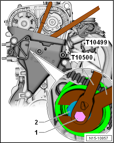
- Loosen bolt -1- using insert tool -T10500-.
- Release the tensioner roller at eccentric -2- using wrench -T10499-.
- Slide the timing belt off the camshaft gears.
Risk of damage to timing belt! The timing belt consists of glass fibre cord fabric. The diameter of the timing belt must therefore never be less than 50 mm (approx. Ø of the crankshaft gear). Falling below this value has a negative effect on the service life of the timing belt.

Note
- A small amount of oil may escape while removing the camshaft adjuster.
- To prevent engine oil from reaching the timing belt, place a rag underneath before removing the camshaft adjuster!
- Unscrew camshaft gear fastening bolt and remove gear.
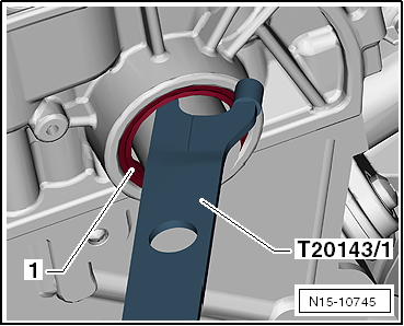
- Pull out seal -1- using extraction hook -T20143/1-.
Installing

Note
Do not oil new seal ring.
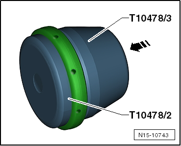
- Join installation sleeves -T10478/2- and -T10478/3- together in the -arrow direction-.
- Slide new seal ring onto installation sleeve -T10478/2- in the -arrow direction-.
- Pull off installation sleeve -T10478/3- in the -arrow direction-.
- Place installation sleeve -T10478/2- with seal ring -1- onto the camshaft.
- Draw in pressure piece -T10478/1- with fastening bolt for camshaft adjuster -2- until it stops.

Note
Bolt -T10478/4- is used to install the seal ring on the exhaust camshaft.
- Set valve timing "Setting valve timing".
Risk of engine damage. After completing the work, make sure that locking bolt -T10340- and camshaft locking tool -T10477- have been removed.
Reassembly is carried out in the reverse order of removal.
Tightening torques
- Coolant pump timing belt cover "Assembly overview - Cylinder head"
- Camshaft gear and tensioner roller fastening bolts "Assembly overview - Cylinder block belt pulley side"


Removing and installing camshaft seal, exhaust camshaft transmission side
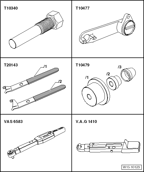
Required Special Tools, Test and Measuring Equipment and Auxiliary Items
- Locking bolt -T10340-
- Camshaft locking tool -T10477-
- Extractor hook -T20143/1-
- Installation device -T10479-
- Torque wrench -VAS 6583-
- Torque wrench -V.A.G 1410-
Required Special Tools, Test and Measuring Equipment and Auxiliary Items
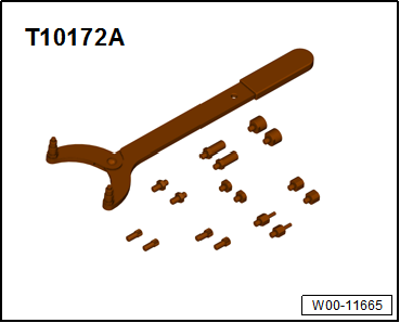
- Counterhold tool -T10172A-
Removing
- Drain coolant “Draining and refilling coolant”.
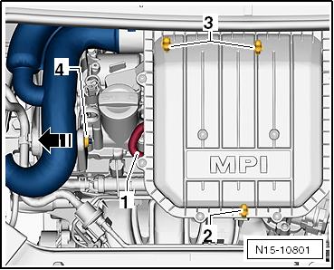
- Disconnect hose -1- from air filter housing.
- Pull air filter housing upward off the bolts at points -2- and -3-.
- Push the air filter housing with the intake connector out of mount -4- in the -arrow direction-.
- Remove the air filter housing from the engine compartment.
- Unlock and disconnect fuel supply line -1- and vent line -2-.
- Open cable routing -3- and remove hoses.
- Plug lines so that no dirt can enter the fuel system.
- Unhook clips -arrow-.
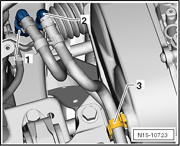
- Unscrew mounting bolt -1- and remove cover -2-.
- Unscrew mounting bolts -arrows-.
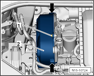
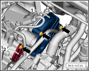
- Unclip line routing from cover.
- Remove cover -1- and cap -2-.
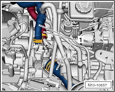
- Disconnect all coolant hoses -1- from the coolant pump.
- Unscrew sealing plug -arrow- from crankcase.
- Lower lift platform fully.

Note
- The lift platform must be lowered fully so that locking bolt -T10340- can be screwed into the crankcase.
- The locking screw is screwed in from above.
- With vehicle raised, the drive shaft is in front of the bore.
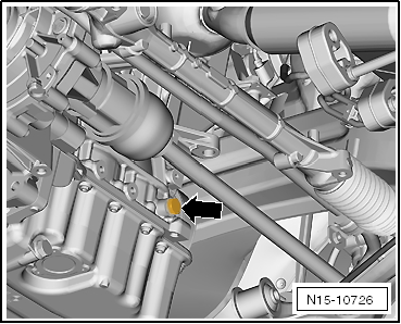
- Screw locking bolt -T10340- into crankcase from above as far as it will go.
- If locking bolt -T10340- cannot be screwed in as far as it will go, the crankshaft is not in the correct position!
- In this case, proceed as described below.
- Unscrew locking bolt.
- Turn crankshaft 90° in direction of engine rotation.
- Turn locking bolt -T10340- into crankcase as far as it will go.
- Tighten locking bolt -T10340- with 30 N·m.
- Turn crankshaft in direction of engine rotation as far as it will go.
The locking bolt -T10340- blocks the crankshaft in the direction of engine rotation.
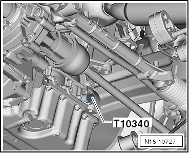
The marked tooth gap -1- of the camshaft adjuster -3- is opposite web -2- on the camshaft housing.

The marked tooth -1- of the exhaust camshaft sprocket -3- is opposite web -2- on the camshaft housing.
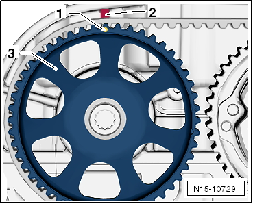
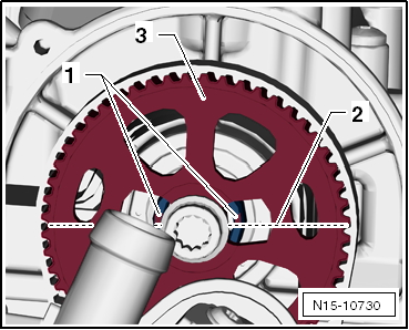
- The slots -1- of the intake camshaft -3- are above the camshaft centerline -2-.
- The slots -1- of the exhaust camshaft are above the camshaft centerline -2-.
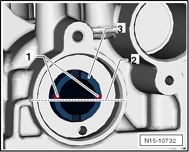
- The cutouts of the gear -3- point slightly upward in the area of the slots.
- The camshaft locking tool -T10477- must fit in easily.
- Do not use a impact tool to install the camshaft locking tool!
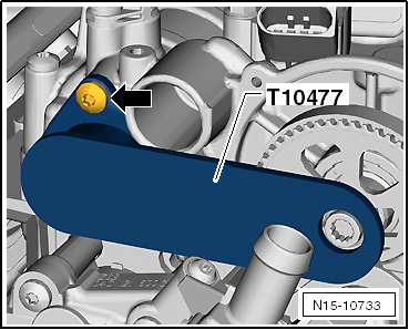
- Insert camshaft locking tool -T10477- into the camshafts as far as it will go and tighten the bolt -arrow- by hand.
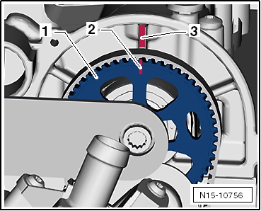
- Mark coolant pump gear -1- with a pin -2- opposite web -3-.

Note
- The marking is necessary so that the gear is later installed in this position.
- Otherwise, camshaft locking tool -T10477- cannot be inserted.
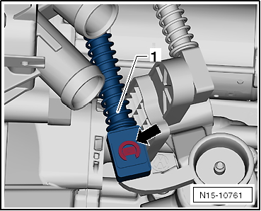
- Remove retaining clip -arrow- of the shift cable.
- Pull cable -1- off the shift lever and set it aside.
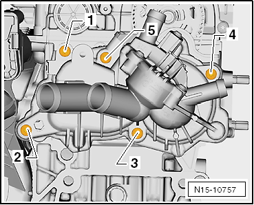
- Unscrew coolant pump fastening bolts in the specified sequence -1- to -5-.
- Remove coolant pump.
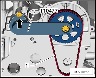
- Unscrew bolt -arrow- and remove camshaft locking tool -T10477- from the camshafts.
- Remove toothed belt -1- from the coolant pump toothed belt pulley.

Note
- The toothed belt must be replaced!
- The coolant pump toothed belt must not be reused, as it no longer builds up the required pre-tension!
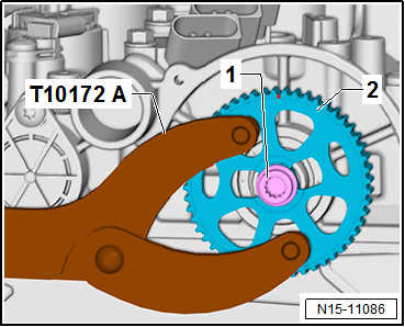
- Hold toothed belt pulley -2- with counter-holder -T10172A- and unscrew retaining bolt -1-.
- Remove toothed belt pulley.
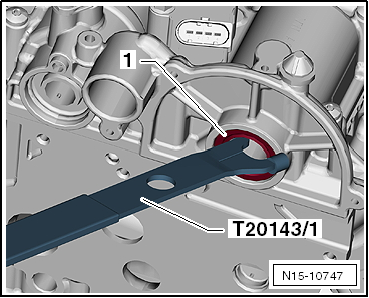
- Carefully insert extractor hook -T20143/1- between camshaft and seal ring -1-.
- Lever out seal ring -1-.
Installing

Note
Do not oil new seal ring.
- Join installation sleeves -T10479/2- and -T10479/3-.
- Slide a new seal ring onto installation sleeve -T10479/2- in the direction of the arrow.
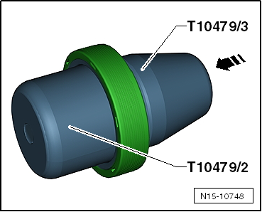
- Separate installation sleeves -T10479/2- and -T10479/3- in the direction of the arrow.
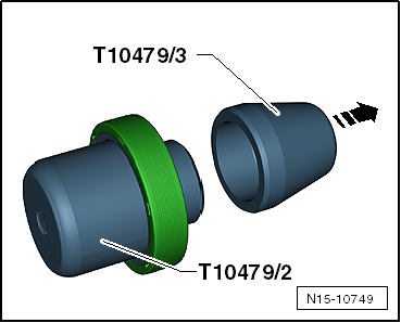
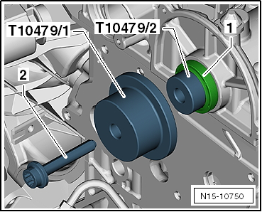
- Place installation sleeve -T10479/2- with seal ring -1- onto the camshaft.
- Slide pressure piece -T1047971- up to the seal ring and press in with retaining bolt -2- until it stops.
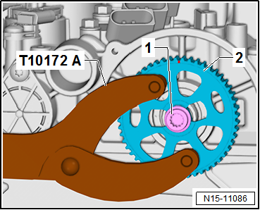
- Position toothed belt pulley -2- on the camshaft and secure with retaining bolt -1-.
Mark on toothed belt pulley must be aligned with the lug.
- Hold toothed belt pulley -2- with counter-holder -T10172A-.
- Tighten mounting bolt -1- to 20 N·m.
- Wet the coolant pump seal with coolant.
- Place toothed belt centrally on the camshaft and coolant pump toothed belt pulleys.
- Install coolant pump. "Removing and installing coolant pump"
- After completing the work, make sure that locking bolt -T10340- and camshaft locking tool -T10477- have been removed.
Reassembly is carried out in the reverse order of removal.
- Install shift linkage on transmission.
- Top up coolant "Draining and topping up coolant".
- Install air filter housing "Removing and installing air filter housing".
Tightening torques
- Crankcase drain plug: 30 N·m
Removing and installing valve stem seals
Required Special Tools, Test and Measuring Equipment and Auxiliary Items
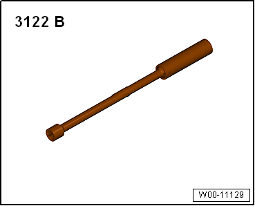
- Spark plug wrench -3122 B-
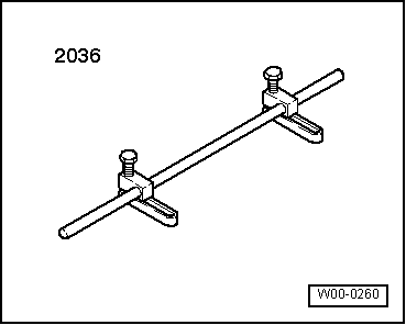
- Valve assembly device -2036-
- Valve stem seal drift -3365-
- Valve lever -VW 541/1 A- (not illustrated)
- Pliers for valve stem seals -VAS 6770- (not illustrated)
Removing
(With cylinder head installed)
- Remove camshaft housing "Removing and installing camshaft housing".
- Remove roller rocker arms and place them on a clean surface. Take care not to mix up the roller rocker arms.
- Unscrew the spark plugs using spark plug socket -3122 B-.
- Set the piston of the respective cylinder to "bottom dead center".

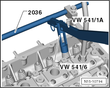
- Insert valve assembly device -2036- and set the mounting to stud bolt height.
- Screw pressure hose -VW 653/3- into the spark plug thread.
- Connect the pressure hose to compressed air of at least 6 bar gauge pressure and remove the valve springs.
- Remove valve springs using valve lever -VW 541/1 A- and pressure piece -VW 541/6-.

Note
Loosen stuck valve collets by tapping lightly with a hammer on the fitting lever.
- Pull off valve stem seals using pliers for valve stem seals -VAS 6770-.
Installing
- Slide the supplied plastic sleeve onto the respective valve stem. This prevents damage to the new valve stem seal.
- Insert the new valve stem seal -1- into valve stem seal drift -3365-.
- Oil the sealing lip of the valve stem seal and carefully slide it over valve stem -2- onto the valve guide.
- Install camshaft housing "Removing and installing camshaft housing".
Reassembly is carried out in the reverse order of removal.

Intake and exhaust valves
Check valve guides
Required Special Tools, Test and Measuring Equipment and Auxiliary Items
- Universal dial gauge holder -VW 387-
- Dial gauge
Test procedure
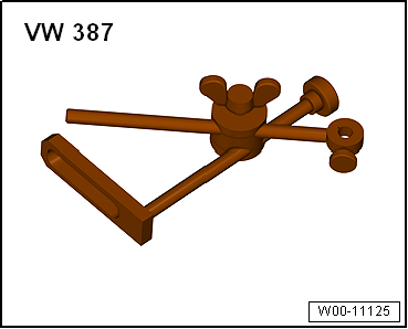
- Insert a new valve into the guide. The valve stem end must be flush with the guide. Due to the different stem diameters, only use intake valves in intake guides and exhaust valves in exhaust guides.
- Determine rocker play by moving the valve in the direction of the arrow.
Wear limit: 0.5 mm
If the wear limit is exceeded:
- Repeat the measurement with a new valve.
If the wear limit is still exceeded:
- Replace cylinder head.
