GENERAL INFORMATION
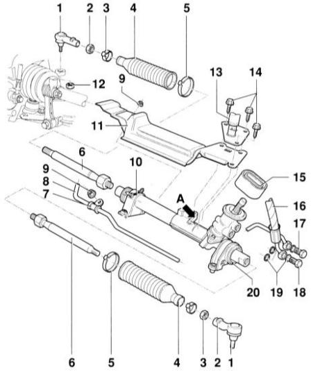 Rack and pinion steering gear with tie rods 1 – tie rod end 2 – nut, 50 N•m 3 – clamp. Always replace 4 – protective boot. Do not remove after toe adjustment. May only be replaced after removing the steering gear (dealer work). 5 – clamp. Always replace 6 – tie rod, 75 N•m. May only be replaced after removing the steering gear (dealer work). 7 – clamp with rubber 8 – return line 9 – nut, 22 N•m 10 – clamp with rubber support. In the installed position the arrow on the clamp points in the direction of travel. If the thread of the welded nut is damaged, replace the clamp. 11 – heat shield 12 – nut, 45 N•m. Self-locking, always replace. 13 – shift drive mount. When installed with heat shield 11, it must be centered on the connector (arrow A). 14 – bolt, 24 N•m 15 – seal 16 – hydraulic line 17 – banjo bolt, 45 N•m. M16 x 1.5 18 – banjo bolt, 40 N•m. M14 x 1.5 19 – O-ring. Always replace 20 – steering gear
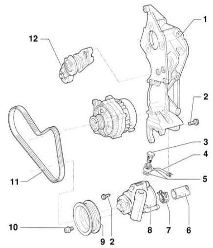 Power steering pump with bracket. Bottom-mounted version 1 – bracket 2 – bolt, 25 N•m 3 – banjo bolt, 30 N•m 4 – pressure hose 5 – O-ring 6 – suction hose 7 – clamp 8 – power steering pump. Fill with oil before removal. To do so, pour oil into the pump suction port and turn the hub by hand so that oil comes out of the pump pressure side. 9 – pulley 10 – socket head screw, 25 N•m 11 – V-ribbed belt 12 – belt tensioner
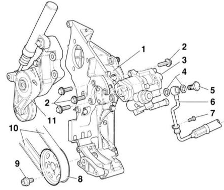 Power steering pump with bracket. Top-mounted version 1 – bracket 2 – bolt, 25 N•m 3 – power steering pump. Fill with oil before removal. To do so, pour oil into the pump suction port and turn the hub by hand so that oil comes out of the pump pressure side. 4 – O-ring. Always replace. 5 – banjo bolt, 30 N•m 6 – pressure hose 7 – bolt, 22 N•m 8 – pulley 9 – socket head screw, 25 N•m 10 – V-ribbed belt 11 – belt tensioner
The driver's steering inputs are transmitted from the steering wheel through the steering column and steering gear to the wheels. The steering column is collapsible, with height adjustment of 44 mm and reach adjustment of 50 mm.
The force required to turn the steering wheel, especially when the vehicle is stationary, is reduced by the hydraulic power steering. The power steering system consists of an oil pump, reservoir and oil lines. The pump is driven by the engine via a V-ribbed belt. The pump draws oil from the reservoir and delivers it under pressure to the control valve housing. The control valve housing is located in the steering gear. It is mechanically linked to the steering gear and, depending on the steering wheel angle, directs oil to the appropriate chamber of the hydraulic cylinder. Here the oil acts on the rack piston and thus assists the movement of the steering.
The airbag is located in the steering wheel. It consists of a folded air bag which, in the event of a frontal collision, inflates and thus protects the driver's head and upper body from striking the steering wheel. In a frontal impact of sufficient force, the control unit ignites a small charge in the airbag module, and the gases generated inflate the air bag within a few milliseconds. This time is sufficient to cushion the driver's forward-moving body. A few seconds later the airbag deflates again, as the gases escape through the vent holes.
CAUTION
Welding and straightening work on steering components is not permitted. Replace self-locking nuts with new ones. In addition to the driver airbag, there are also a front passenger airbag and front and rear side airbags. If a rear-facing child seat is installed in the front passenger seat, the front passenger airbag must be deactivated. This work may only be performed by an AUDI dealer. In addition, the warning label "No child seat in front" must be placed on the door pillar, sun visor or instrument panel on the right side of the vehicle, otherwise the driver may be fined during a traffic police inspection.When equipping the vehicle with side airbags for the seat backrests, use only special upholstery approved by AUDI.
When removing and installing the airbag control unit
PROCEDURE
1. Disconnect the negative (–) battery cable with the ignition switched off.
CAUTION
: As a result, information stored in the electronic memory modules, such as the radio code, is erased. Without the code, the radio can only be activated by the manufacturer or an AUDI dealer. Therefore, refer to the section Entering the radio code.2. Disconnect the negative (–) battery terminal to prevent accidental contact.
3. Set the wheels straight.
CAUTION
If the above notes are not observed, the airbag system may fail during further operation.General Notes
– After electrically connecting the airbag, turn the ignition on with the ignition key in the "Drive" position before connecting the battery. – Do not allow unauthorized persons to remain in the vehicle when connecting the battery. – After removing the airbag, store it with the soft side facing up. – Do not leave the airbag unattended if work is interrupted. – Do not disassemble the airbag control unit. If faulty, replace it as a complete assembly. Since the airbag contains explosive material, store it securely. The airbag must be disposed of by an AUDI dealer service center. – Check the airbag only at an AUDI dealer service center. Never use a test lamp, voltmeter or ohmmeter to check the airbag. – Do not expose the airbag to liquids, in particular grease or any cleaning agents. – If the airbag has been dropped onto a hard surface, it must no longer be used.
Test yourself
A quick Audi A3 quiz: every answer comes with an explanation and a link to the manual page.