Wheel Hub and Bearing
GENERAL INFORMATION
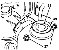
Telescopic strut mounting to body
36. Upper mount protective cap.
37. NUT (TIGHTENING TORQUE 30 N·m.
39. UPPER (BEARING) STRUT MOUNT
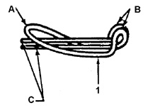
Spring clip A. REAR DOOR BRACKET.
B. FRONT HINGES.
C. LATCH.
1. SPRING CLIP
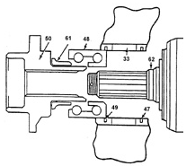
Hub bearing support
33. STRUT BEARING SUPPORT.
47. GROOVE FOR SNAP RING (INTERNAL).
48. BEARING.
49. GROOVE FOR SNAP RING (EXTERNAL).
50. HUB.
61. BEARING INNER RING.
62. AXLE SHAFT
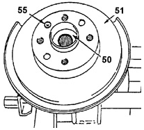
Brake disc set screw
Remove or disconnect
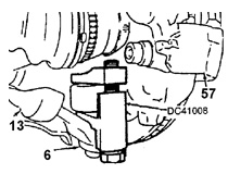
Removal of lower arm ball joint
6. LOWER ARM BALL JOINT.
13. Lower arm.
57. DISC BRAKE CALIPER BRACKET

Removal of axle shaft from hub. A. NUT.
B. BOLT.
C. THRUST BEARING.
33. STRUT WITH BEARING SUPPORT
PROCEDURE.
1. Loosen the two nuts 37 securing the upper strut mount..
2. Loosen the front wheel mounting bolts. Remove cotter pin 54, then loosen nut 55.
axle shaft and remove the washer.
53..
3. Raise the vehicle.
4. Place support stands under the vehicle.
5. Lower the vehicle slightly so that it rests on the stands, but not on the lower arms.
6. Front wheels.
Warning.
Make sure that after removing the nuts, the axle shafts do not come out of the internal
sliding joints. This will disassemble the joints. Damage to the joints is also possible.
When working in the area of the joints,
install protective boots over the rubber
dust seals of the joints. Otherwise, damage to parts or seals and joint failure may occur.
parts or seals of the joints and joint failure.
7. Remove brake caliper bracket 57 from the bearing support. After removal, be sure to
secure the bracket to avoid damaging the brake hoses..
8. Bolt
56..
9. Brake disc
52..
10. Nuts of the steering knuckle ball joints.
Warning.
To remove the outer tie rod ball joints, use
puller KM-507B.
11. Spring clip 1 nut
2..
11a. Lift the rear retainer tab and remove the clip by its front loops.
12. Remove the nut.
2..
13. Using puller KM-507B, disconnect the ball joint stud from the hole.
bearing support bracket..
Warning.
When using puller KM-507B to remove ball joints, do not
pay attention to the marking "THIS SIDE TOWARD WHEEL" stamped on the tool..
14. Disconnect the axle shaft from the hub..
15. Secure the axle shaft..
16. Lower the vehicle to remove the two nuts 37 with washers
38..
17. Strut assembly 33..
Warning.
When removing the springs and performing further work on them, do not allow chips or
scratches on the spring coil coating..
Disassemble
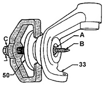
Wheel hub removal A. NUT.
B. BOLT.
C. BEARING.
33. TELESCOPIC STRUT BEARING SUPPORT.
50. HUB
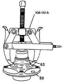
Bearing inner race removal
50. HUB.
63. BEARING INNER RACE
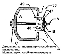
Bearing removal and installation A. BOLT.
B. NUT.
C. BEARING.
33. STRUT BEARING SUPPORT.
47. SNAP RING. REMOVE BEFORE REMOVING BEARING. INSTALL IN PLACE AFTER INSTALLING HUB 50.
48. BEARING.
49. SNAP RING. REMOVE BEFORE REMOVING BEARING. INSTALL IN PLACE BEFORE INSTALLING BEARING.
PROCEDURE.
1. Remove hub 50 from the bearing.
48..
2. Using puller KM-161A, remove the bearing inner race 61 from the hub.
50..
Warning.
Before removing bearing 48 from support 33, remove the snap rings.
47 and
49..
3. Remove the bearing.
48. The removed bearing must not be
reused.
Clean.
PROCEDURE.
Bearing seat bore in the bearing support
33..
Assembly
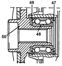
Snap ring installation
47. SNAP RING (INTERNAL).
48. BEARING.
49. SNAP RING (EXTERNAL).
50. HUB
PROCEDURE.
1. Install snap ring 49 into the groove before installing the bearing. Snap ring 47 is installed into the groove after installing the hub.
50..
2. Insert the bearing..
3. Install hub 50 into the bearing.
48..
4. Install the snap ring in place.
47..
Install or connect
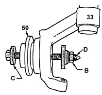
Wheel hub installation A. INSTALL INTERNAL SNAP RING IN PLACE AFTER INSTALLING HUB.
B. NUT.
C. BEARING.
D. BOLT.
33. STRUT BEARING SUPPORT.
50. HUB
PROCEDURE.
1. Remove the protective boot from the joint..
2. Insert the axle shaft into the splined hole of the hub
50. Install onto the shaft.
washer and a new nut onto the axle shaft. Before assembly, check the lubrication in the axle shaft joints. Add the specified grease if necessary. Do not tighten nut 55 until the wheel is installed and the vehicle is lowered to the ground..
3. Ball joint to the bearing support
33..
4. Nut
2..
5. Tie rod ball joint to the steering knuckle arm
33. Tighten the nut.
tie rod ball joint nut to the specified torque 60 N·m. Secure the nut with a cotter pin.
(if equipped). Tighten the lower ball joint mounting nut
arm to the specified torque 70 N·m. Install the spring retainer..
6. Brake disc and set screw. Tighten the brake disc set screw
to the specified torque 4 N·m..
7. Disc brake caliper..
8. Wheel..
9. Raise the vehicle slightly..
10. Remove the support stands..
11. Lower the vehicle..
12. Tighten the wheel bolts in a crisscross sequence to the specified torque 90 N·m..
13. Tighten the axle shaft nut to the specified torque 100 N·m..
Use only a new castellated nut..
14. Loosen the axle shaft nut and retighten it to the specified torque 20 N·m..
15. Turn the axle shaft nut an additional 1/4 turn. If the nut slot does not
align with the cotter pin hole in the axle shaft stub, further tightening of the nut is prohibited. In this case, loosen the nut and repeat all operations
from the beginning.
Test yourself
A quick Daewoo Nexia quiz: every answer comes with an explanation and a link to the manual page.