Upper Mount
GENERAL INFORMATION
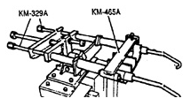
Spring compressor tools

Strut mount bearing
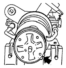
Location of spring seat
Remove or disconnect
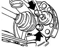
Removal of protective caps
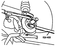
Removal of cotter pin
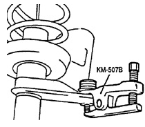
Removal of ball joint

Removal of driveshaft
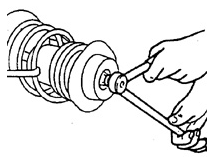
Removal of strut mount bearing
PROCEDURE.
1. Raise the vehicle and remove the front wheel..
2. Protective cap..
3. Remove the disc brake caliper and secure it. (The brake hose must remain connected and the brake system must stay sealed)..
4. Install holder KM-468 to the hub with two wheel bolts..
Use the wheel mounting bolts..
5. Remove the cotter pin and loosen the driveshaft castle nut..
6. Press the ball joint stud out of the steering knuckle using puller KM-507B..
7. Press the lower arm ball joint stud out of the bearing housing using puller KM-507B..
8. Pull the driveshaft out of the wheel hub by hand. If this is not possible, press the driveshaft out using the hub puller, installed in position.
Press the driveshaft out using the hub puller, installed in position.
to press out..
9. Secure the driveshaft so it is not loaded..
Warning.
After removing the driveshaft, do not load the wheel or move the vehicle with the
driveshaft removed, as this may cause axial displacement of the inner bearing ring.
bearing. If the vehicle must be moved, temporarily install a threaded tie rod into the hub and tighten the castle nut. (This will secure the position of the bearing rings).
bearing will be secured)..
10. Remove the strut upper mount nuts and remove the strut assembly..
11. Install spring compressors KM-465A and KM-329A on the front suspension spring. Mount the strut on a workbench or stand where the base can be fixed for
installation of the tools.
The hook with the blue mark must be aligned with the yellow mark on the tool frame..
12. Secure the strut in the compressor..
13. Check the position of the hooks. Compress the spring..
14. Holding the strut damper rod from turning, loosen the upper mount nut using an open-end wrench.
It is recommended to use a commercially available double-ended offset wrench.
15. Remove the strut upper mount assembly with the bearing from the damper rod..
Install or connect
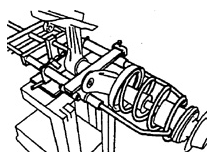
Installing the strut in the compressor

Installing protective caps
PROCEDURE.
1. Lubricate the ball bearing with bearing grease. The strut upper mount is a non-disassemblable design and is supplied only as an assembly with the ball bearing..
2. Install the upper mount and washers A and B onto the damper rod. Cup washer A must be positioned under the mount with the bent edge facing up. This metal washer acts as a moving seal for the ball bearing by contact of the washer edge with the outer bearing ring. Install washer B on the rod from above..
3. The projection on the spring seat serves as a reference for strut installation. When viewed in the direction of vehicle travel, the projection on the left strut mount must face forward, and the projection on the right strut mount must face rearward..
4. Tighten the strut mounting nut with an open-end wrench. Use only a new self-locking nut. Tighten the nut to the specified torque. When tightening the nut, hold the damper rod from turning..
5. Release the spring compressor..
6. Install the strut on the vehicle and secure the upper mount in its seat..
Tighten the nuts to the specified torque. Use only new self-locking nuts..
7. Insert the driveshaft into the splined hole of the wheel hub and install the castle nut. Use only a new nut and washer. Before installation, lubricate the splines with transmission fluid..
8. Connect the ball joint to the strut bearing housing and tighten the nut to the specified torque. Install the spring cotter pin. Use only a new castle nut and cotter pin..
9. Connect the steering tie rod ball joint to the steering knuckle. Tighten the nut to the specified torque. Use only a new self-locking nut..
Warning.
There must be no play in the wheel bearing..
10. Install the driveshaft as follows.
10a. Insert the driveshaft into the hub and tighten the castle nut (with washer) to a torque of 100 N·m. Attach holder KM-468 to the hub beforehand to prevent the hub from rotating..
10b. Loosen the driveshaft castle nut, then tighten it to a torque of 20.
N·m..
10c. Turn the driveshaft nut an additional 1/4 turn..
10d. If the nut slot does not align with the cotter pin hole in the driveshaft stub,
do not tighten the nut further. In this case, loosen the nut until the cotter pin hole aligns with the nut slot. Secure the nut with a cotter pin.
11. Install the disc brake caliper bracket on the strut bearing housing. Tighten the threaded connections to the specified torque. Before installation, apply thread-locking compound to the new bolts (if the bolts do not have a factory coating). Chase the threaded hole with an M 12 x 1, tap.
5..
12. Using installer tools KM-404-A and KM-404-C, fully seat the protective caps onto the disc brake caliper bracket. Use new caps..
13. Tighten the wheel bolts in a crisscross pattern to the specified torque.
Test yourself
A quick Daewoo Nexia quiz: every answer comes with an explanation and a link to the manual page.