Weber 2V carburettor - removal and refitting
Removal
1 Disconnect the battery negative lead. 2 Remove the air cleaner as described in Section 2.
3 Disconnect the electrical leads at the electric choke and anti-run-on valve (see illustration).

16.3 Weber 2V carburettor disconnection points - XR3 models
A Anti-run-on valve lead B Electric choke lead
C Throttle cable
8 Refitting is the reverse sequence to removal, but use a new flange gasket and ensure that the mating surfaces are perfectly clean. Make sure that the vacuum pipe fuel trap is correctly positioned, and on completion check the idle speed and mixture settings as described in Chapter 1. 1.4 litre models
9 The procedure is identical to that just described for XR3 models except that a manual choke is fitted and the choke inner cable must be released by slackening the linkage clamp bolt. 10 Additionally when refitting, observe the following points. a) Adjust the choke cable as described in Section 9.
b) Where applicable, the lead for the antirun- on valve should be removed from the metal clip which secures it to the carburettor body, re-routed as shown, and taped to the vacuum hose (see illustrations). The metal clip should be discarded, and the securing screw refitted to the carburettor body, ensuring it is fully tightened.

16.10a Removing the metal clip (A) securing the anti-run-on valve lead (B) 1.4 litre models

16.10b Correct routing of the anti-run-on valve lead - 1.4 litre models
A Anti-run-on valve
B Lead
C Lead taped to
vacuum hose
11 Disconnect the battery negative lead. 12 Remove the air cleaner as described in Section 2. 13 If the engine is still hot, depressurise the cooling system by carefully releasing the pressure cap (see Chapter 1). 14 Disconnect the coolant inlet and outlet hoses at the automatic choke and clamp or plug their ends to prevent coolant loss. 15 Disconnect the throttle cable by releasing the spring clip securing the end fitting to the ball-stud, then unscrewing the cable bracket fixing bolts. 16 Disconnect the fuel inlet and return hoses, noting their respective positions, and plug them after removal. If crimped type clips are used, cut them off and use screw type clips when refitting. 17 Disconnect the distributor vacuum pipe and the throttle kicker vacuum pipe on automatic transmission models. 18 Disconnect the electrical lead at the antirun- on valve solenoid.
19 Using a suitable Torx type key or socket bit, unscrew the four mounting through-bolts from the top of the carburettor and remove the unit from the manifold (see illustration).
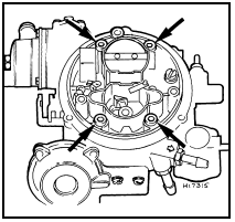
16.19 Weber 2V carburettor mounting through-bolt locations - 1.6 litre models Refitting 20 Refitting is the reverse sequence to removal, but use a new flange gasket and ensure that the mating faces are perfectly clean. On completion top-up the cooling system as described in “Weekly checks” and check the idle speed and mixture settings as described in Chapter 1. 1.1 and 1.3 litre HCS engine models
Removal
21 Disconnect the battery negative terminal. 22 Remove the air cleaner as described earlier. 23 Disconnect the throttle and choke cables as described in the relevant Sections. 24 Disconnect the fuel inlet hose. If crimped connections are used cut them off and renew them with screw type clips.
25 Disconnect the lead at the anti-run-on valve solenoid (see illustration).

16.25 Anti-run-on valve solenoid (arrowed) - 1.1 and 1.3 litre HCS engines
26 Remove the four Torx type through-bolts securing the carburettor to the inlet manifold (see illustration).
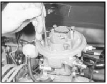
16.26 Removing a Torx through-bolt - 1.1 and 1.3 litre HCS engines
27 Lift off the carburettor (see illustration).
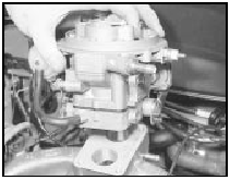
16.27 Lifting off the carburettor - 1.1 and 1.3 litre HCS engines Refitting 28 Refit in reverse order using a new flange gasket.
29 On completion check the idle speed and mixture settings as described earlier.
Test yourself
A quick Ford Escort quiz: every answer comes with an explanation and a link to the manual page.