Installation - Engine
Special Service Tools / General Equipment
 |
303-050 (T70P-6000) Engine Lift Bracket |
| Adjustable mounting arm | |
| Vehicle/Axle Stands | |
| Cable Ties | |
| Hose Clamp Removal/Installation Tool | |
| Wood block | |
Materials
| Name | Specification |
|---|---|
| Motorcraft® Silicone Brake Caliper Grease and Dielectric Compound XG-3-A |
ESE-M1C171-A |
NOTICE: Turbocharger compressor blades can be damaged by even the smallest particles. When removing any turbocharger or engine air intake system component, make sure that debris does not enter the system. Failure to do so may result in damage to the turbocharger.
Left Full-Time 4WD/Left Rear-Wheel Drive
- Inspect the turbocharger or engine air intake system components and clean them as necessary.
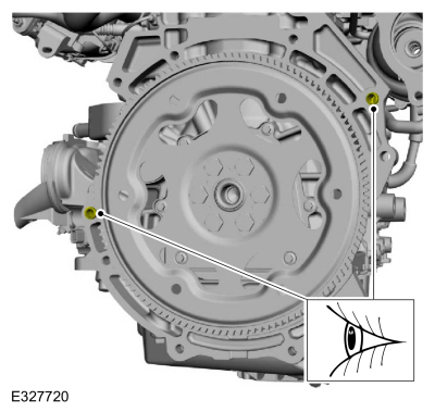
- Inspect the cylinder block dowels. If the dowels are damaged or missing, install new cylinder block dowels.
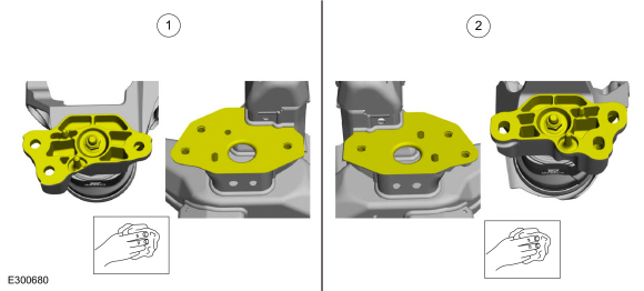
- Before installation, clean the mating surfaces of the left engine mount and the frame of dirt or foreign material.
- Before installation, clean the mating surfaces of the right engine mount bracket and the frame of dirt or foreign material.
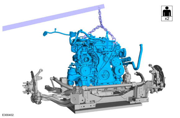
- With the help of an assistant, using a floor crane and chain, install the engine to the subframe.
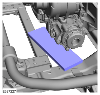
- Make sure the board is still supporting the engine.
- Install the right engine mount bolts and tighten them in the sequence shown.
Torque: 76 lb-ft (103 N·m)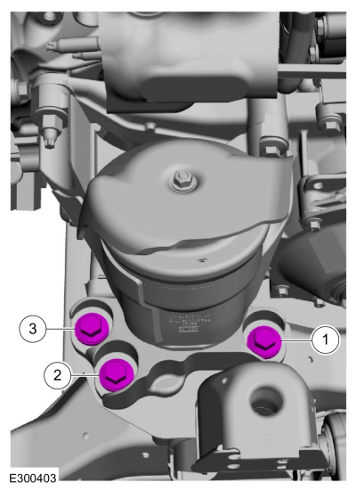
- Install the left engine mount bolts and tighten them in the sequence shown.
Torque: 76 lb-ft (103 N·m)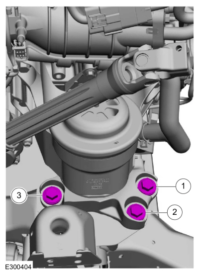
- Install and tighten the adjustable mounting link bolts.
Use common service equipment: adjustable mounting link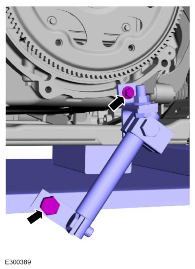
- Remove the floor crane and chain.
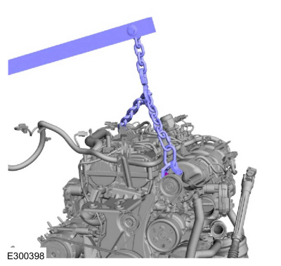
- Remove the Special Service Tool: 303-050 (T70P-6000) Engine Lift Bracket.
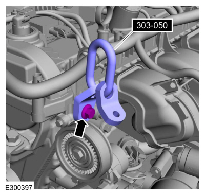
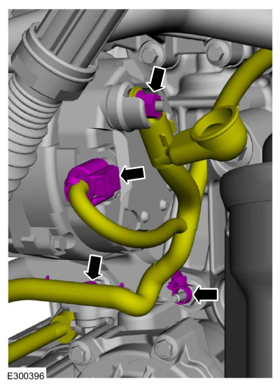
- Attach the wiring harness retainers.
- Connect the generator electrical connector.
- Position the B+ wire and install the nut.
Torque: 155 lb-in (17.5 N·m)
- Install the B+ wire protective cover.
- Position the ground wire on the engine block and install the bolt and wiring harness retainer.
Torque: 106 lb-in (12 N·m)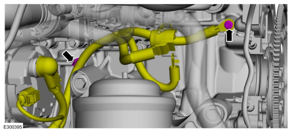
- Install the starter motor and connect the engine control wire to the starter motor, then install the nut.
Torque: 53 lb-in (6 N·m)
- Connect the positive battery cable to the starter motor and install the nut.
Torque: 106 lb-in (12 N·m)
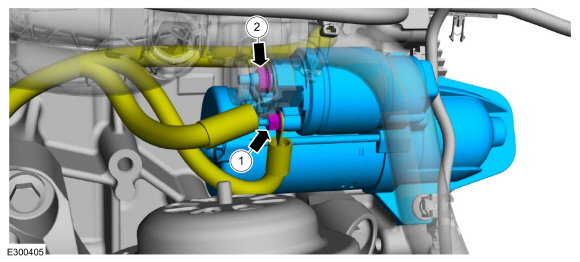
- Install the starter motor and connect the engine control wire to the starter motor, then install the nut.
- Install the auxiliary coolant pump, hoses and bolt.
Torque: 97 lb-in (11 N·m)
- Install the coolant hose clamp and retainer.
Use common service equipment: hose clamp removal/installation tool.
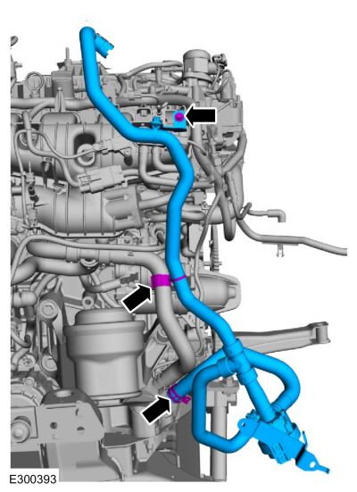
- Install the auxiliary coolant pump, hoses and bolt.
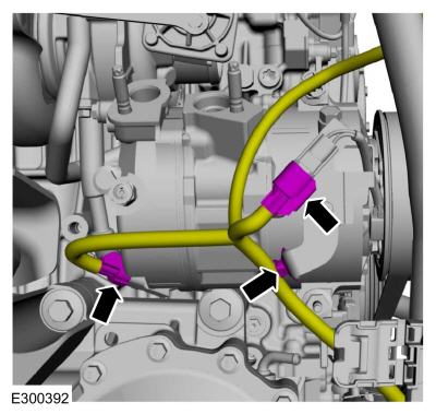
- Connect the air conditioning compressor electrical connectors and the wiring harness retainer.
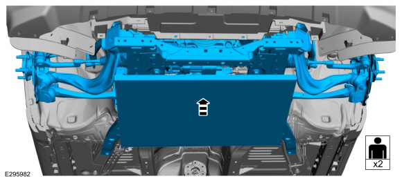
- With the help of an assistant and using the powertrain jack, raise the powertrain and subframe assembly 25.4 mm (1 in) from the frame.
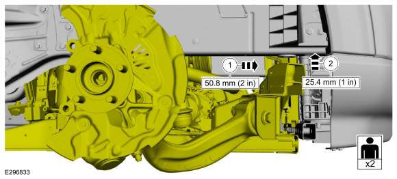
- With the help of an assistant and using the powertrain jack, move the powertrain and subframe assembly forward 50.8 mm (2 in).
- With the help of an assistant and using the transmission jack, raise the transmission and subframe 25.4 mm (1 in).
- Hand-tighten the new rear subframe bolts.
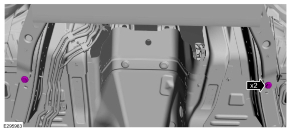
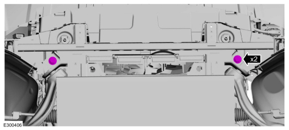
- Hand-tighten the new front subframe bolts.
- Hand-tighten the new center subframe bolts.
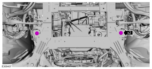
- Tighten the rear subframe bolts.
Torque: 52 lb-ft (70 N·m) - Tighten the front subframe bolts.
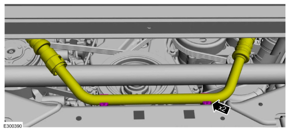
Torque: 195 lb-ft (265 N·m) - Attach the coolant tube retainers to the front of the subframe.
- Install the radiator upper support beam bolts.
Torque: 46 lb-ft (63 N·m)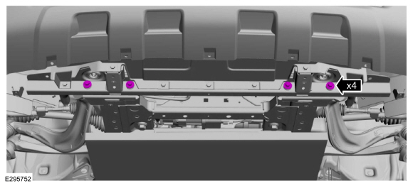
- Discard.
Use common shop equipment: adjustable mount link - Remove the powertrain jack and wooden blocks.
Use common service equipment: wooden block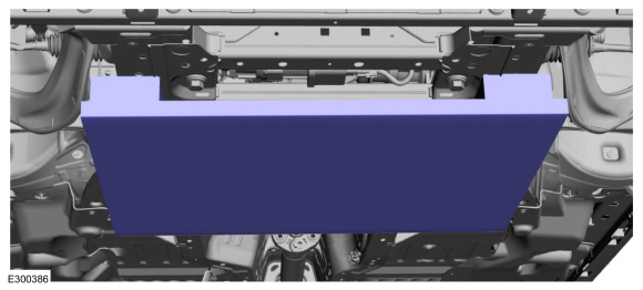
- Tighten the center subframe bolts.
Torque: 195 lb-ft (265 N·m) - Position the left underbody shield and install the bolt.
Torque: 22 lb-in (2.5 N·m)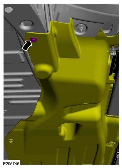
- Position the right underbody shield and install the bolt.
Torque: 22 lb-in (2.5 N·m)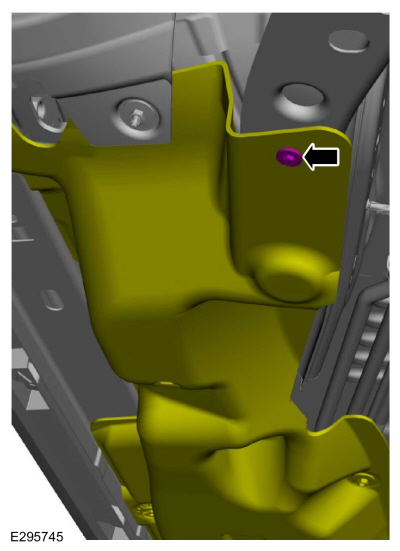
left rear
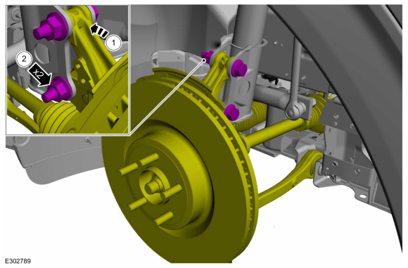
- On both sides, insert the steering knuckle into the front strut and spring assembly.
- Install the new lower strut-to-steering knuckle nuts and bolts.
Torque: 166 lb-ft (225 N·m)
- On both sides, install the wheel speed sensor and bolt.
Torque: 106 lb-in (12 N·m)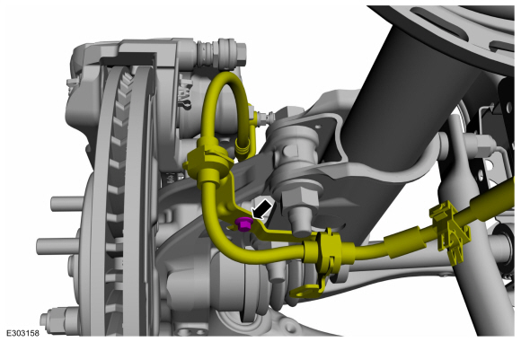
- On both sides, install the front brake hose and bolt.
Torque: 133 lb-in (15 N·m)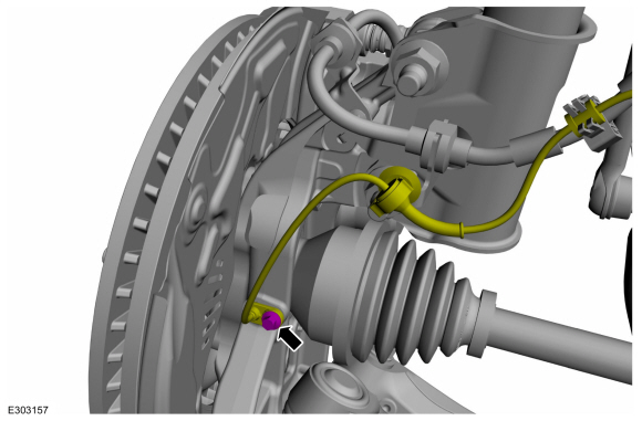
Left Full-Time 4WD/Left Rear-Wheel Drive
NOTICE: Use the internal or external hex feature to prevent the ball stud from turning when removing or installing the stabilizer link nut. The protective link boot must not rotate while tightening the link nuts or damage the boot seal.
Position the right stabilizer bar link and install a new nut.
Torque: 129 lb-ft (175 N·m)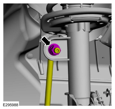
NOTICE: Use the internal or external hex feature to prevent the ball stud from turning when removing or installing the stabilizer link nut. The protective link boot must not rotate while tightening the link nuts or damage the boot seal.
Position the left stabilizer bar link and install a new nut.
Torque: 129 lb-ft (175 N·m)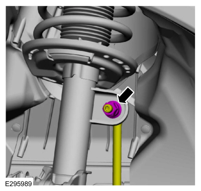
- Position the splash shield and install the pin retainer to the left subframe.
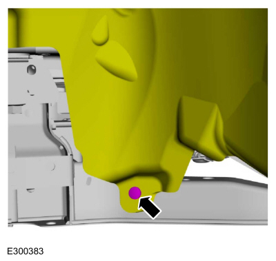
- If equipped, install the steering gear shield and pin-type retainers on the left subframe.
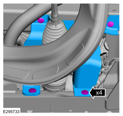
- If equipped with all-wheel drive, install the left fender splash shield nut.
Torque: 22 lb-in (2.5 N·m)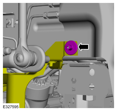
- Attach the HO2S sensor wire harness retainers to the right subframe.
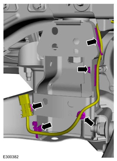
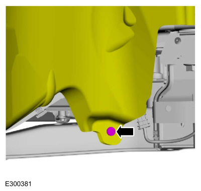
- Install the splash shield pin retainer to the right subframe.
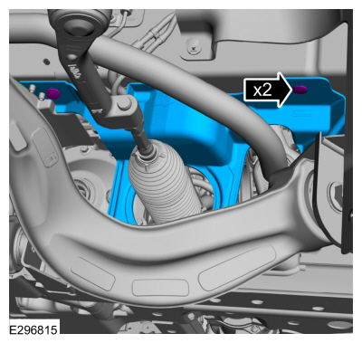
- If equipped, install the steering gear shield and pin-type retainers on the right subframe.
- If equipped with all-wheel drive, install the right fender splash shield nut.
Torque: 22 lb-in (2.5 N·m)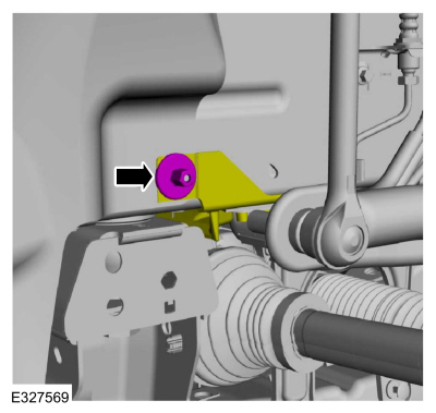
- If equipped, install the steering gear shroud pin clips to the right subframe.
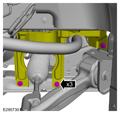
- Install the auxiliary coolant pump and install the bolts.
Torque: 80 lb-in (9 N·m)
- Connect the electrical connector of the auxiliary coolant pump wire harness and the retainer.
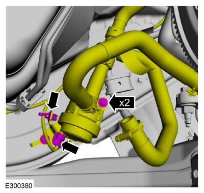
- Install the auxiliary coolant pump and install the bolts.
- Install the transmission oil cooler and connect the coolant tube.
- Install the transmission oil cooler coolant tube and tighten the clamp.
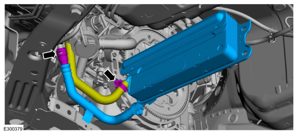
- Install the stand.
Use common service equipment: vehicle/axle stands.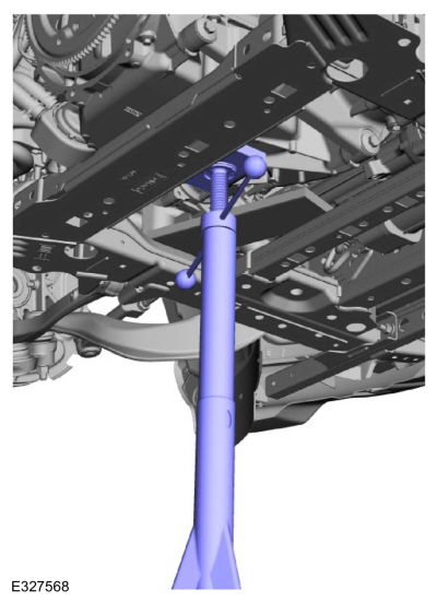
- Remove the board.
Use common service equipment: wooden block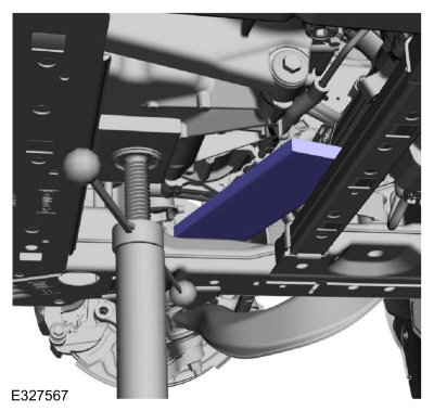
- Install the transmission.
Refer to: Transmission — 2.3 L EcoBoost (201 kW/273 L PS) (307-01A Automatic Transmission — 10-Speed Automatic Transmission — 10R60, Removal and Installation).
Left Full-Time 4WD
- Connect the wiring harness electrical connector to the front axle assembly.
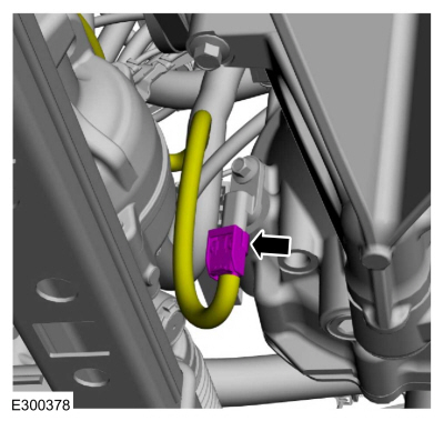
- Connect the wiring harness electrical connector to the left axle connector.
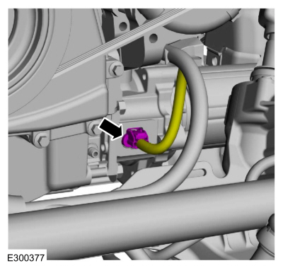
- Position the vent tubes and connect the vent hose to the front axle assembly.
- Attach the wiring harness retainer to the vent tubes.
- Connect the vent hose to the left axle connector.
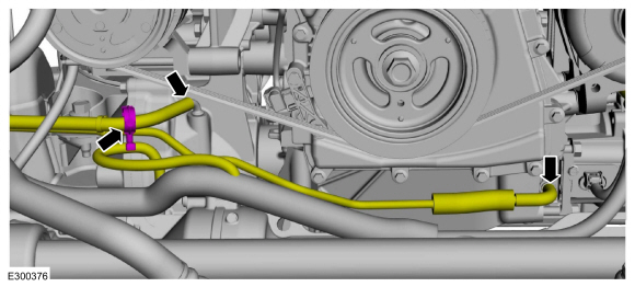
- Install the right and left half shafts.
Refer to: Half Shaft (205-04 Front-Wheel Drive Half Shafts, Removal and Installation).
Left Full-Time 4WD/Left Rear-Wheel Drive
NOTICE: Do not allow the brake caliper and anchor plate assembly to hang from the brake hose, as the hose may be damaged.
Install both front brake discs.
Refer to: Brake Disc (206-03 Front Disc Brake, Removal and Installation).- Lubricate the sealing surface of the new engine oil filter with clean engine oil and install it.
Torque:
Stage 1: 71 lb-in (8 N·m)
Stage 2: 180 degrees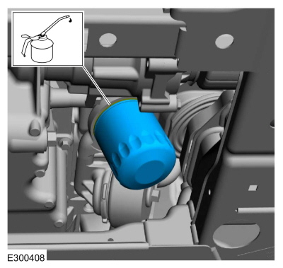
- Install the rear lower engine splash shield.
Refer to: Rear Lower Engine Shield (501-02 Front Body Panels, Removal and Installation). - Position the wiring harness and bracket, and install the bolt to the frame rail.
Torque: 106 lb-in (12 N·m)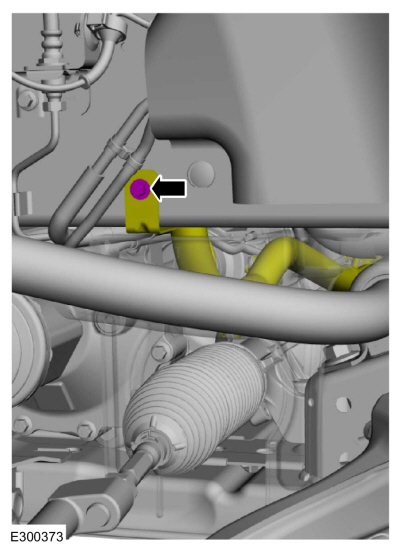
- Install the left and right front wheels and tires.
Refer to: Wheels and Tires (204-04A Wheels and Tires, Removal and Installation). - Position the wiring harness and install the wiring harness lock nut.
Torque: 106 lb-in (12 N·m)
- Position the ground wire and install the bolt.
Torque: 106 lb.in (12 N·m)
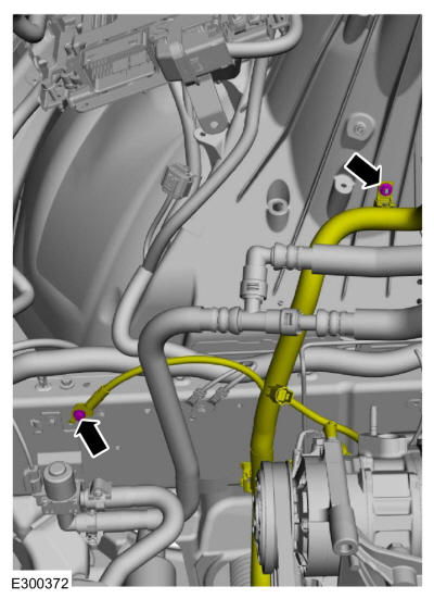
- Position the wiring harness and install the wiring harness lock nut.
- Install the wiring harness cable tie.
Use common equipment: cable ties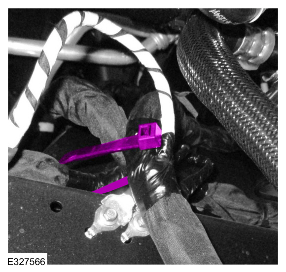
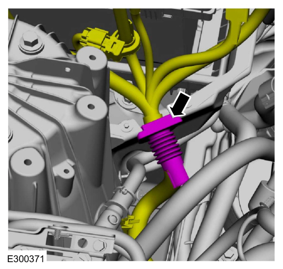
- Install the wiring harness electrical grommet.
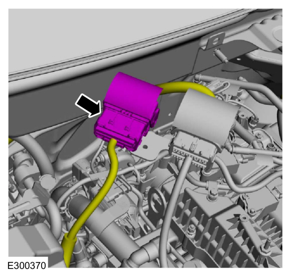
- Connect the wiring harness electrical connector.
- Position the battery wiring harness and install the nut.
Torque: 48 lb-in (5.4 N·m)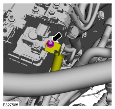
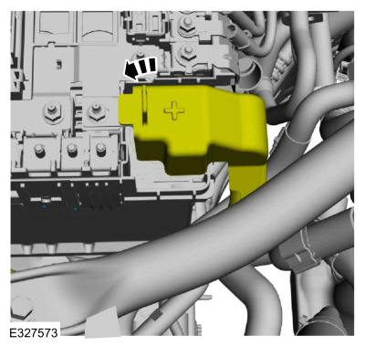
- Position the battery cable cover over the battery cable.
- Position the ground and install the bolt.
Torque: 106 lb-in (12 N·m)
- Position the battery B+ cables and install the nuts.
Torque: 80 lb-in (9 N·m)
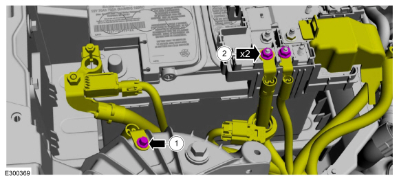
- Position the ground and install the bolt.
- Install the cover.
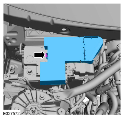
- Connect the fuel feed tube quick-connect coupling.
Refer to: Quick-Connect Coupling (310-00 Fuel System - General Information).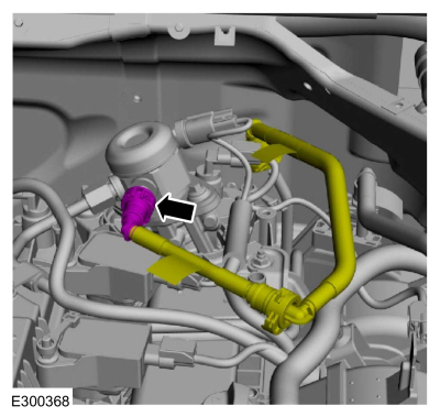
- Install the high-pressure fuel pump insulator.
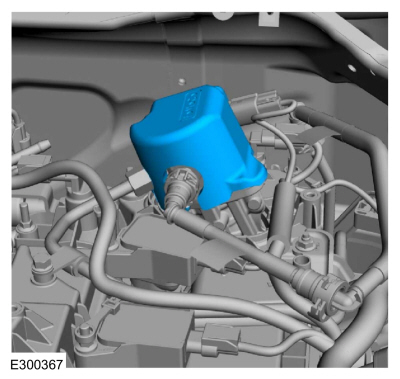
- Position the coolant tubes and attach the fuel tube clip.
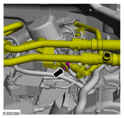
- Position the coolant tubes and install the bolt.
Torque: 124 lb-in (14 N·m)
- Install the coolant tubes nut.
Torque: 62 lb-in (7 N·m)
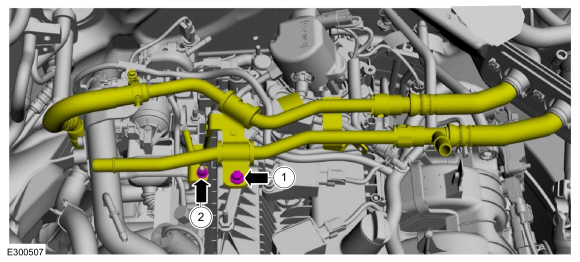
- Position the coolant tubes and install the bolt.
- Connect the coolant tube to the coolant hoses located above the engine.
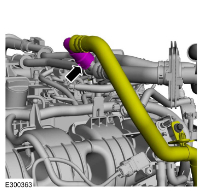
- Position the lower coolant hose and install the clamp and clip.
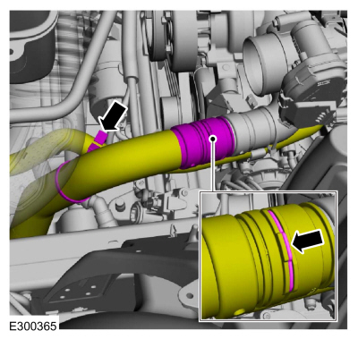
- Install new O-rings.
- Connect the A/C lines and install the nuts.
Torque: 133 lb-in (15 N·m)
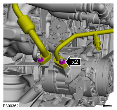
- Connect the A/C pressure sensor and attach the wiring harness clip.
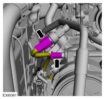
- Position and connect the coolant hose quick-connect couplings.
- Position the coolant hose and install the clamp.
Use common service equipment: hose clamp removal and installation tool.
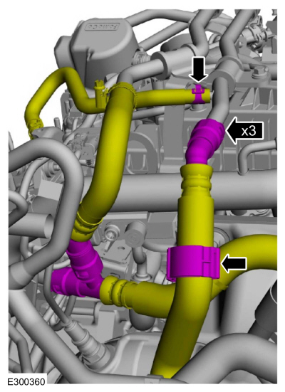
- Connect the upper radiator hose to the coolant outlet and tighten the clamp.
Torque: 44 lb-in (5 N·m)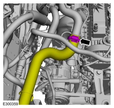
- Position the coolant hose from the coolant recovery reservoir, tighten the clamp and attach the coolant hose bracket.
Torque: 44 lb-in (5 N·m)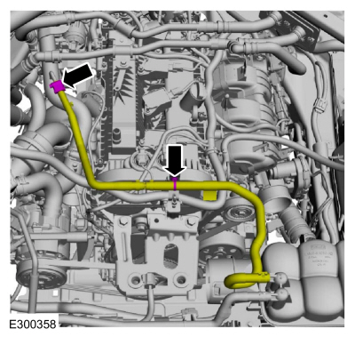
- Position and connect the engine wiring harness electrical connector and clip.
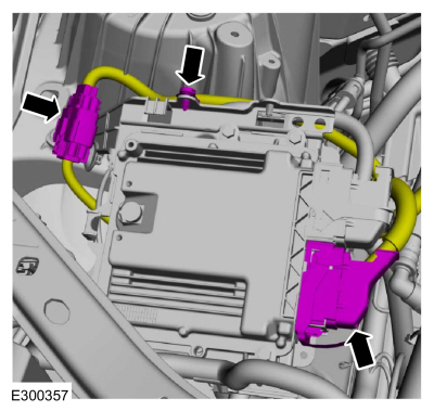
- Connect the PCM electrical connector.
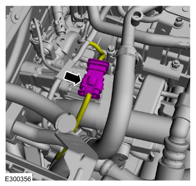
- Connect the HO2S sensor electrical connector.
- Install a new steering shaft bolt.
Torque: 22 lb-ft (30 N·m)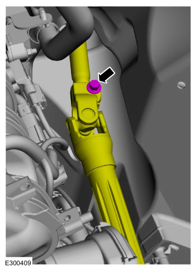
- Position the coolant hose and install the clamp.
Use common service equipment: hose clamp removal and installation tool.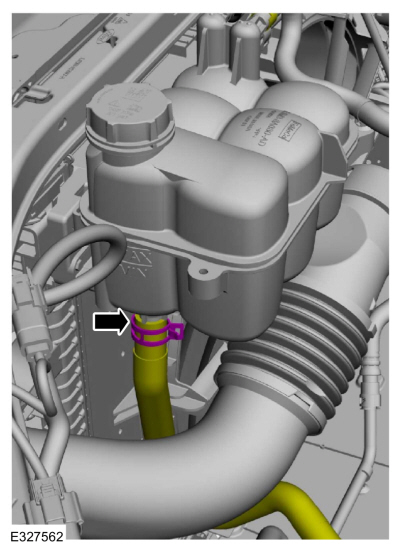
- If equipped, position the block heater wiring harness and attach the clips.
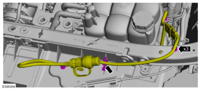
- Position the ground wire, install the bolt and attach the retainers.
Torque: 159 lb-in (18 N·m)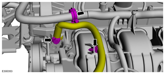
- Install the shield and bolts (Torx PLUS® or hex head, Acument Intellectual Properties, LLC as owner).
Torque: 18 lb-ft (25 N·m)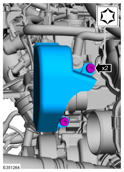
- Position the CAC tube clamp and tighten the clamp.
Torque: 44 lb-in (5 N·m)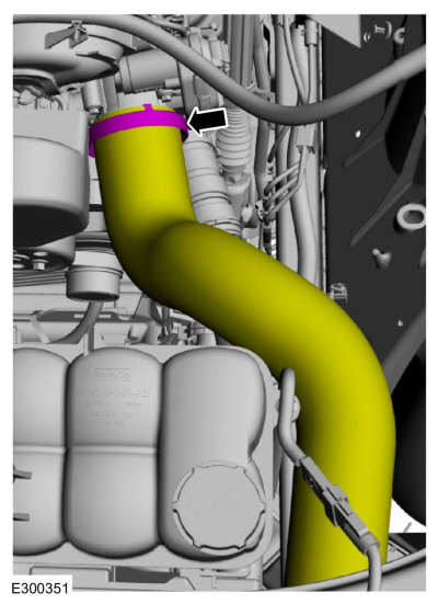
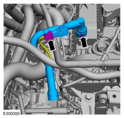
- Install a new crankcase vent tube.
- If the replacement crankcase vent tube is supplied without the crankcase pressure sensor, reprogram the PCM.
Refer to: Module Programming (418-01 Module Configuration, General Procedures).
- If the replacement crankcase vent tube is supplied without the crankcase pressure sensor, wrap the electrical connector of the wiring harness and return it to the wiring harness.
- If the replacement crankcase vent tube is supplied with the crankcase pressure sensor, connect the wiring harness electrical connector.
- Remove the cable ties or mechanical wires supporting the cooling module.
Use common equipment: cable ties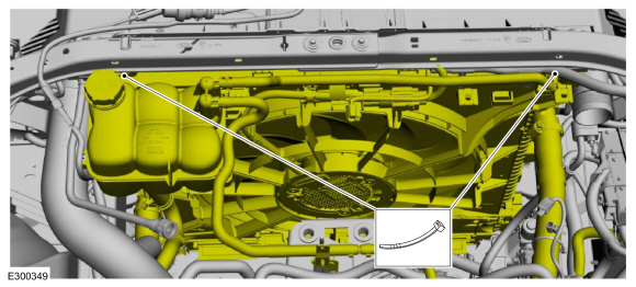
- Install the EVAP canister tube and connect the quick-connect coupling to the intake manifold.
Refer to: Quick-Connect Coupling (310-00 Fuel System - General Information).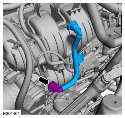
- Install the EVAP canister tube and connect the quick-connect coupling and clip.
Refer to: Quick-Connect Coupling (310-00 Fuel System - General Information).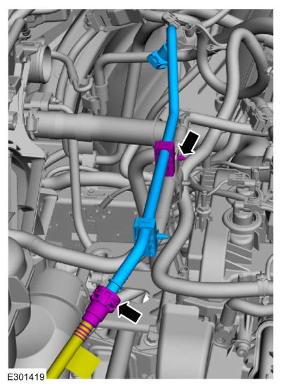
- Install the following components:
- Install the air cleaner outlet pipe.
Refer to: Air Cleaner Outlet Pipe (303-12A Intake Air Distribution and Filtration - 2.3 L EcoBoost (201 kW/273 L hp), Removal and Installation). - Install the CAC inlet tube.
Refer to: Charge Air Cooler (CAC) Inlet Pipe (303-12A Intake Air Distribution and Filtration — 2.3 L EcoBoost (201 kW/273 L hp), Removal and Installation). - Install the air cleaner.
Refer to: Air Cleaner (303-12A Intake Air Distribution and Filtration — 2.3 L EcoBoost (201 kW/273 L hp), Removal and Installation). - Install the EVAP canister purge valve.
Refer to: Evaporative Emission Canister Purge Valve (303-13A Evaporative Emission System - 2.3 L EcoBoost (201 kW/273 L hp), Removal and Installation). - Install the hood panel.
Refer to: Hood Panel (501-02 Front End Body Panels, Removal and Installation).
- Install the air cleaner outlet pipe.
- Lubricate each bushing with silicone grease.
Material: Motorcraft® Silicone Brake Caliper Grease and Dielectric Compound / XG-3-A (ESE-M1C171-A)
- Position the engine appearance cover on the engine, aligning the bushing with the stud.
- Press the engine appearance cover at the bushing location to attach the bushing to the stud and install the nuts.
Torque: 44 lb-in (5 N·m)
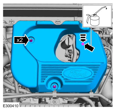
- Lubricate each bushing with silicone grease.
- Install the suspension crossmember and bolts.
Torque: 22 lb-ft (30 N·m)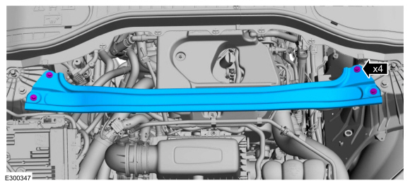
- Remove the restraint device.
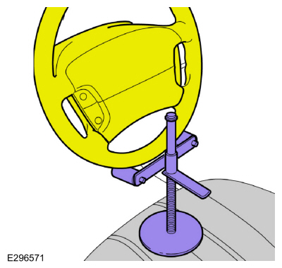
- Fill the engine with clean engine oil.
Refer to: Specifications (Engine 303-01A - 2.3 L EcoBoost (201 kW/273 L PS), Specifications).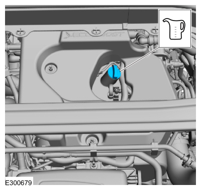
- Connect the positive and negative battery cables.
Refer to: Battery Disconnect and Connect (414-01 Battery, Mounting and Cables). - Charge the A/C system.
Refer to: Refrigerant Recovery, Evacuation and Charging (A/C) - Vehicles With: R1234YF Refrigerant (412-00 Climate Control System - General Information, General Procedures). - Build up fuel system pressure.
Refer to: Fuel System Pressure Release (310-00A Fuel System — General Information — 2.3 L EcoBoost (201 kW/273 L PS), General Procedures). - Fill the cooling system.
Refer to: Engine Cooling System Draining, Vacuum Filling and Air Bleeding (303-03A Engine Cooling — 2.3 L EcoBoost (201 kW/273 L hp), General Procedures). - Check the transmission fluid level.
Refer to: Transmission Fluid Level Check (307-01A Automatic Transmission — 10-Speed Automatic Transmission — 10R60, General Procedures). - Start the engine and check the exhaust system for leaks.
- Use the Powertrain Control Module (PCM) misfire monitor profile correction procedure with the diagnostic scan tool.
Test yourself
A quick Ford Explorer quiz: every answer comes with an explanation and a link to the manual page.