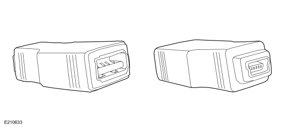
If the LHF door speaker is the concern, go to Pinpoint Test H.
If the LHF door tweeter is the concern, go to Pinpoint Test I.
B1A01:11
Speaker No. 1: Short to Ground
If the LHF door speaker is the concern, go to Pinpoint Test H.
If the LHF door tweeter is the concern, go to Pinpoint Test I.
B1A01:12
Speaker No. 1: Short to Battery
If the LHF door speaker is the concern, go to Pinpoint Test H.
If the LHF door tweeter is the concern, go to Pinpoint Test I.
B1A01:13
Speaker No. 1: Open Circuit
GO to Pinpoint Test H
B1A02:01
Speaker No. 2: General Electrical Failure
If the RHF door speaker is the concern, go to Pinpoint Test J.
If the RHF door tweeter is the concern, go to Pinpoint Test K.
B1A02:11
Speaker No. 2: Short to Ground
If the RHF door speaker is the concern, go to Pinpoint Test J.
If the RHF door tweeter is the concern, go to Pinpoint Test K.
B1A02:12
Speaker No. 2: Short to Battery
If the RHF door speaker is the concern, go to Pinpoint Test J.
If the RHF door tweeter is the concern, go to Pinpoint Test K.
B1A02:13
Speaker No. 2: Open Circuit
GO to Pinpoint Test J
B1A03:01
Speaker No. 3: General Electrical Failure
GO to Pinpoint Test L
B1A03:11
Speaker No. 3: Short to Ground
GO to Pinpoint Test L
B1A03:12
Speaker No. 3: Short to Battery
GO to Pinpoint Test L
B1A03:13
Speaker No. 3: Open Circuit
GO to Pinpoint Test L
B1A04:01
Speaker No. 4: General Electrical Failure
GO to Pinpoint Test M
B1A04:11
Speaker No. 4: Short to Ground
GO to Pinpoint Test M
B1A04:12
Speaker No. 4: Short to Battery
GO to Pinpoint Test M
B1A04:13
Speaker No. 4: Open Circuit
GO to Pinpoint Test M
B1A56:21
Antenna: Signal Amplitude < Minimum
If DTC B1A56:21 is set after running the faceplate diagnostic tests, DO NOT consider this DTC. This test is used for end-of-line testing or repair station testing at the vehicle assembly plant. Each plant is assigned its own frequency and signal strength requirements. Passing or failing this test depends on local radio stations. If no local station is broadcasting on the required frequency, the test fails.
B1A89:11
Satellite Antenna: Short to Ground
If the concern is satellite radio, go to Pinpoint Test B.
If the concern is SIRIUS Travel Link, GO to Pinpoint Test C.
For navigation (if equipped), GO to Pinpoint Test Y.
If the concern is the compass, go to Pinpoint Test Z.
B1A89:13
Satellite Antenna: Open Circuit
If the concern is satellite radio, go to Pinpoint Test B.
If the concern is SIRIUS Travel Link, GO to Pinpoint Test C.
For navigation (if equipped), GO to Pinpoint Test Y.
If the concern is the compass, go to Pinpoint Test Z.
B1D19:49
CD Unit: Internal Electronic Failure
GO to Pinpoint Test V
B1D19:4B
CD: Overtemperature
GO to Pinpoint Test V
U0155:00
Lost communication with IPC module: no subtype information
GO to Pinpoint Test advertisement
U0253:00
Lost Communication with Auxiliary Protocol Interface Module: No Sub Type Information
GO to Pinpoint Test AH
U0256:00
Lost communication with the Front Controls Interface Module "A": no sub-type information
GO TO Pinpoint Test AI
U201A: 51
Control Module Primary Calibration Data: Not Programmed
This DTC is set due to incorrect or incomplete ACM configuration. Using the diagnostic scan tool, PERFORM the ACM programming procedure using the original data. For configuration data, refer to Refer to: Module Configuration - System Operation and Component Description (418-01 Module Configuration, Description and Operation). See configuration data.
U2100:00
Initial Configuration Not Complete: No Sub Type Information
This DTC is set due to incorrect or incomplete ACM configuration. Using the diagnostic scan tool, PERFORM the ACM programming procedure using the original data. For configuration data, refer to Refer to: Module Configuration - System Operation and Component Description (418-01 Module Configuration, Description and Operation). See configuration data.
U2101:00
Control Module Configuration Incompatible: No Sub Type Information
This DTC is set due to incorrect or incomplete ACM configuration. Using the diagnostic scan tool, PERFORM the ACM programming procedure using the original data. For configuration data, refer to Refer to: Module Configuration - System Operation and Component Description (418-01 Module Configuration, Description and Operation). See configuration data.
U3000:41
Control Module: General Checksum Failure
CLEAR the DTCs.
WAIT at least 10 seconds.
REPEAT the self-test.
If DTC U3000:41 recurs, INSTALL a new ACM. Refer to: Front Audio Control Module (ACM) (415-00A Information and Entertainment System - General Information - Vehicles With: AM/FM/CD/SYNC, Removal and Installation).
U3000:42
Control Module: General Memory Failure
CLEAR the DTCs.
WAIT at least 10 seconds.
REPEAT the self-test.
If DTC U3000:42 recurs, INSTALL a new ACM. Refer to: Front Audio Control Module (ACM) (415-00A Information and Entertainment System - General Information - Vehicles With: AM/FM/CD/SYNC, Removal and Installation).
U3000:96
Control Module: Internal Component Failure
CLEAR the DTCs.
WAIT at least 10 seconds.
REPEAT the self-test.
If DTC U3000:96 recurs, INSTALL a new ACM. Refer to: Front Audio Control Module (ACM) (415-00A Information and Entertainment System - General Information - Vehicles With: AM/FM/CD/SYNC, Removal and Installation).
U3003:16
Battery Voltage: Circuit Voltage Below Threshold
GO TO Pinpoint Test AJ
U3003:17
Battery Voltage: Circuit Voltage Above Threshold
GO to Pinpoint Test AK
DTC Chart: APIM
Trouble Code
Description
Action
B108E:01
Display: General Electrical Failure
GO to Pinpoint Test W
B108E:12
Display: Battery Short to Ground
GO to Pinpoint Test W
B108E: 63
Display: Circuit/Component Protection Time-out
GO to Pinpoint Test W
B119F:01
GPS Antenna: General Electrical Failure
For navigation (if equipped), GO to Pinpoint Test Y.
If the concern is the compass, go to Pinpoint Test Z.
B119F: 13
GPS Antenna: Circuit Open
For navigation (if equipped), GO to Pinpoint Test Y.
If the concern is the compass, go to Pinpoint Test Z.
B11BA:1C
Audio System Steering Wheel Switch Block: Circuit Voltage Out of Range
GO to Pinpoint Test U
B11BA:63
Audio System Steering Wheel Switch Block: Circuit/Component Protection Time-Out
GO to Pinpoint Test U
B1252:11
USB Port: Short to Ground
GO to Pinpoint Test Q
B1252:13
USB Port: Circuit Open
GO to Pinpoint Test Q
B12B8:11
USB Port No. 2: Short to Ground
INSPECT the APIM USB Port No. 2 for damage and REMOVE any debris.
CLEAR the diagnostic trouble codes (DTCs).
WAIT at least 10 seconds.
REPEAT the APIM self-test.
If DTC B12B8:11 is retrieved again, PERFORM the APIM hardware check.
PERFORM THE FDRS PROGRAM
NOTE: This procedure must be performed using FDRS. Do not clear DTCs until the FDRS procedure is complete. To complete the diagnosis, go to the FDRS Step-by-Step Procedure tab and perform the SYNC procedure.
B14FD:11
Multimedia External Control Connection: Circuit Short to Ground
GO to Pinpoint Test Q
B1D79:11
Microphone Input: Short to Ground
GO to Pinpoint Test P
B1D79:12
Microphone Input: Short to Battery
GO to Pinpoint Test P
B1D79:13
Microphone Input: Circuit Open
GO to Pinpoint Test P
C1001:01
Vision System Camera: General Electrical Failure
REFER TO: Parking Aid System (413-13B Parking Aid System - Vehicles With: Parking Aid Camera, Diagnosis and Testing). See Rear Video Inoperative.
U0121:00
Lost Communication with Anti-Lock Braking System (ABS) Control Module: No Sub-Type Information
GO TO Pinpoint Test AA
U0140:00
Lost Communication With Body Control Module: No Sub Type Information
GO to Pinpoint Test AB
U0151:00
Lost Communication with Restraints Control Module: No Sub Type Information
GO to Pinpoint Test AC
U0155:00
Lost communication with instrument cluster IPC module: no subtype information
GO to Pinpoint Test advertisement
U0159:00
Park Assist Control Module "A" Lost Communication: No Sub Type Information
GO TO Pinpoint Test AF
U0162:00
Navigation Display Module Lost Communication: No Sub Type Information
GO to Pinpoint Test W
U0184:00
Lost Communication With Radio: No Sub Type Information
GO to Pinpoint Test AG
U0256:00
Lost communication with the Front Controls Interface Module "A": no sub-type information
GO TO Pinpoint Test AI
U0415:00
Incorrect Data Received from Anti-Lock Braking System (ABS) Control Module: No Sub-Type Information
RETRIEVE and RECORD the DTCs present in the ABS module. REFER TO: Anti-Lock Brake System (ABS) and Stability Control System (206-09 Anti-Lock Brake System (ABS) and Stability Control System, Diagnosis and Testing). • If no DTCs are present in the ABS module, DIAGNOSE the observed symptom.
U0422:00
Incorrect Data Received from Body Control Module: No Sub Type Information
RETRIEVE any Diagnostic Trouble Codes (DTCs) stored in the BCM and FOLLOW them. REFER TO: Body Control Module (BCM) (419-10 Multifunction Electronic Modules, Diagnosis and Testing). • If there are no DTCs stored in the BCM, PERFORM DIAGNOSIS of the observed symptom.
U0423:00
Invalid Data Received from Instrument Panel Control Module: No Sub-type Information
RETRIEVE and MONITOR any Diagnostic Trouble Codes (DTCs) present in the IPC. REFER TO: Instrument Cluster, Message Center and Warning Chimes (413-01 Instrument Cluster, Message Center and Warning Chimes, Diagnosis and Testing). • If there are no DTCs present in the IPC, PERFORM DIAGNOSIS of the observed symptom.
U0452:00
Incorrect Data Received from Restraints Control Module: No Sub Type Information
RETRIEVE and MONITOR any Diagnostic Trouble Codes (DTCs) present in the RCM. REFER TO: Supplemental Restraint System (SRS) (501-20 Supplemental Restraint System). • If there are no DTCs present in the RCM, PERFORM DIAGNOSIS of the observed symptom.
U1A00:87
Private Communication Network: No Sub Type Information
If the concern is satellite radio, go to Pinpoint Test B.
If the concern is SIRIUS Travel Link, GO to Pinpoint Test C.
For navigation (if equipped), GO to Pinpoint Test Y.
If the concern is the compass, go to Pinpoint Test Z.
U2017: 45
Control Module No. 2 Software: Software Memory Failure
CLEAR all Continuous Memory Diagnostic Trouble Codes (CMDTCs).
WAIT at least 10 seconds.
RETRIEVE all Continuous Memory Diagnostic Trouble Codes (CMDTCs).
If DTC U2017:45 is retrieved again, PERFORM the APIM hardware check.
PERFORM THE FDRS PROGRAM
NOTE: This procedure must be performed using FDRS. Do not clear DTCs until the FDRS procedure is complete. To complete the diagnosis, go to the FDRS Step-by-Step Procedure tab and perform the SYNC procedure.
U2017: 51
Control Module No. 2 Software: Not Programmed
This DTC is set due to incorrect or incomplete APIM programming/software. Using the diagnostic scan tool, PERFORM the APIM programming procedure. REFER TO: SYNC Module [APIM] Programming (415-00B Information and Entertainment System - General Information - Vehicles With: AM/FM/CD/SYNC/Touchscreen Display, General Procedures).
U2017: 52
Control Module No. 2 Software: Not Activated
This DTC is set due to incorrect or incomplete APIM programming/software. Using the diagnostic scan tool, PERFORM the APIM programming procedure. REFER TO: SYNC Module [APIM] Programming (415-00B Information and Entertainment System - General Information - Vehicles With: AM/FM/CD/SYNC/Touchscreen Display, General Procedures).
U2017: 54
Control Module No. 2 Software: Calibration Missing
This DTC is set due to incorrect or incomplete APIM programming/software. Using the diagnostic scan tool, PERFORM the APIM programming procedure. REFER TO: SYNC Module [APIM] Programming (415-00B Information and Entertainment System - General Information - Vehicles With: AM/FM/CD/SYNC/Touchscreen Display, General Procedures).
U2100:00
Initial Configuration Not Complete: No Sub Type Information
This DTC is set due to incorrect or incomplete APIM programming/software. Using the diagnostic scan tool, PERFORM the APIM programming procedure. REFER TO: SYNC Module [APIM] Programming (415-00B Information and Entertainment System - General Information - Vehicles With: AM/FM/CD/SYNC/Touchscreen Display, General Procedures).
U2101:00
Control Module Configuration Incompatible: No Sub Type Information
This DTC is set due to incorrect or incomplete APIM programming/software. Using the diagnostic scan tool, PERFORM the APIM programming procedure. REFER TO: SYNC Module [APIM] Programming (415-00B Information and Entertainment System - General Information - Vehicles With: AM/FM/CD/SYNC/Touchscreen Display, General Procedures).
U3000:04
Control Module: Internal System Failure
CLEAR all Continuous Memory Diagnostic Trouble Codes (CMDTCs).
WAIT at least 10 seconds.
RETRIEVE all Continuous Memory Diagnostic Trouble Codes (CMDTCs).
If DTC U3000:04 is retrieved again, PERFORM the APIM hardware check.
PERFORM THE FDRS PROGRAM
NOTE: This procedure must be performed using FDRS. Do not clear DTCs until the FDRS procedure is complete. To complete the diagnosis, go to the FDRS Step-by-Step Procedure tab and perform the SYNC procedure.
U3000:09
Control Module: Component Failure
CLEAR all Continuous Memory Diagnostic Trouble Codes (CMDTCs).
WAIT at least 10 seconds.
RETRIEVE all Continuous Memory Diagnostic Trouble Codes (CMDTCs).
If DTC U3000:09 is retrieved again, PERFORM the APIM hardware check.
PERFORM THE FDRS PROGRAM
NOTE: This procedure must be performed using FDRS. Do not clear DTCs until the FDRS procedure is complete. To complete the diagnosis, go to the FDRS Step-by-Step Procedure tab and perform the SYNC procedure.
U3000:41
Control Module: General Checksum Failure
CLEAR the diagnostic trouble codes (DTCs).
WAIT at least 10 seconds.
REPEAT the APIM self-test.
If DTC U3000:41 is retrieved again, PERFORM the APIM hardware check.
PERFORM THE FDRS PROGRAM
NOTE: This procedure must be performed using FDRS. Do not clear DTCs until the FDRS procedure is complete. To complete the diagnosis, go to the FDRS Step-by-Step Procedure tab and perform the SYNC procedure.
U3000:88
Control Module: Bus Off
To avoid repeated network issues:
CHECK the APIM wiring for damage or corrosion. For circuit and connector information, refer to Cell 14 of the Wiring Diagrams.
CLEAR all Continuous Memory Diagnostic Trouble Codes (CMDTCs).
WAIT at least 10 seconds.
REPEAT the network test using the diagnostic scan tool.
U3003:16
Battery Voltage: Circuit Voltage Below Threshold
GO TO Pinpoint Test AJ
U3003:17
Battery Voltage: Circuit Voltage Above Threshold
GO to Pinpoint Test AK
DTC Chart: FCIM
Trouble Code
Description
Action
U0009:88 (Sony® FCIM only)
High Speed CAN Communication Bus (-) Shorted to Bus (+): Bus Off
The module was unable to establish network communication at a specific point in time. The fault is not present at this time (the module had to communicate with the diagnostic scan tool to report this DTC). CHECK the connectors and wiring for integrity.
U0155:00 (Sony® FCIM only)
Lost Communication with Instrument Panel Cluster (IPC) Control Module: No Sub Type Information
GO to Pinpoint Test advertisement
U0155:87 (FCIM without brand name only)
Lost Communication with Instrument Panel Cluster (IPC) Control Module: No Sub Type Information
GO TO Pinpoint Test AE
U0423:00 (Sony® FCIM only)
Invalid Data Received from Instrument Panel Control Module: No Sub-type Information
RETRIEVE and MONITOR any Diagnostic Trouble Codes (DTCs) present in the IPC. REFER TO: Instrument Cluster, Message Center and Warning Chimes (413-01 Instrument Cluster, Message Center and Warning Chimes, Diagnosis and Testing). • If there are no DTCs present in the IPC, PERFORM DIAGNOSIS of the observed symptom.
If DTC U2013:63 is retrieved again, INSTALL a new FCIM. REFER TO: Front Control Interface Module (FCIM) (415-00B Information and Entertainment System - General Information - Vehicles With: AM/FM/CD/SYNC/Touchscreen Display, Removal and Installation).
U201A:51 (FCIM without brand name only)
Control Module Primary Calibration Data: Not Programmed
This DTC is set due to incorrect or incomplete FCIM configuration. Using the diagnostic scan tool, PERFORM the FCIM programming procedure using the original configuration data. For configuration data information, refer to REFER TO: Module Configuration - System Operation and Component Description (418-01 Module Configuration, Description and Operation). See the configuration data.
U3000:41
Control Module: General Checksum Failure
CLEAR the diagnostic trouble codes (DTCs).
WAIT at least 10 seconds.
REPEAT the self-test.
If DTC U3000:41 is retrieved again, INSTALL a new FCIM. REFER TO: Front Control Interface Module (FCIM) (415-00B Information and Entertainment System - General Information - Vehicles With: AM/FM/CD/SYNC/Touchscreen Display, Removal and Installation).
U3000:42
Control Module: General Memory Failure
CLEAR the diagnostic trouble codes (DTCs).
WAIT at least 10 seconds.
REPEAT the self-test.
If DTC U3000:42 is retrieved again, INSTALL a new FCIM. REFER TO: Front Control Interface Module (FCIM) (415-00B Information and Entertainment System - General Information - Vehicles With: AM/FM/CD/SYNC/Touchscreen Display, Removal and Installation).
U3003:16
Battery Voltage: Circuit Voltage Below Threshold
GO TO Pinpoint Test AJ
U3003:17
Battery Voltage: Circuit Voltage Above Threshold
GO to Pinpoint Test AK
Symptom Charts
Symptom Chart: Display
Condition
Possible Sources
Action
Navigation does not operate or operates incorrectly - if equipped
Refer to Pinpoint Test
GO to Pinpoint Test Y
SIRIUS Travel Link does not operate or operates incorrectly - if equipped with navigation
Refer to Pinpoint Test
GO to Pinpoint Test C
Compass inoperative or operates incorrectly
Refer to Pinpoint Test
GO to Pinpoint Test Z
FDIM is blank or black
Refer to Pinpoint Test
GO to Pinpoint Test W
Image displayed on the FDIM is incorrect, image color is incorrect, image is distorted, flickers or is blurred.
Refer to Pinpoint Test
GO to Pinpoint Test W
Image on the FDIM is locked or frozen
Refer to Pinpoint Test
GO to Pinpoint Test W
FDIM changes brightness
Refer to Pinpoint Test
GO TO Pinpoint Test X
FDIM does not respond to touch
Refer to Pinpoint Test
GO to Pinpoint Test W
FDIM responds slowly to touch
Refer to Pinpoint Test
GO to Pinpoint Test W
Symptom Chart: Media/Phone
Condition
Possible Sources
Action
All APIM mono outputs do not operate or operate incorrectly REFER TO: Information and Entertainment System - System Operation and Component Description (415-00B Information and Entertainment System - General Information - Vehicles With: AM/FM/CD/SYNC/Touchscreen Display, Description and Operation). See the APIM mono outputs list.
Refer to Pinpoint Test
GO to Pinpoint Test N
All APIM stereo outputs do not operate or operate incorrectly REFER TO: Information and Entertainment System - System Operation and Component Description (415-00B Information and Entertainment System - General Information - Vehicles With: AM/FM/CD/SYNC/Touchscreen Display, Description and Operation). See the APIM stereo outputs list.
Refer to Pinpoint Test
GO TO Pinpoint Test O
Bluetooth does not operate or operates incorrectly
Refer to Pinpoint Test
GO to Pinpoint Test S
SYNC® AppLink™ does not operate or operates incorrectly
Refer to Pinpoint Test
INSTRUCT the customer to check the mobile device platform, application and application version compatibility list. REFER TO: owner.ford.com/how-tos/sync-technology/all/phone-setup/how-your-device-works-with-sync.html or es.owner.ford.com/how-tos/sync-technology/all/phone-setup/how-your-device-works-with-sync.html. This is normal operation for incompatible mobile device platforms, applications and application versions that are not available through SYNC® AppLink™.
If the mobile device platform, application and application version are compatible, and the device is connected only via Bluetooth, GO to Pinpoint Test S
If the mobile device platform, application and application version are compatible, and the device is connected via Bluetooth and USB port, GO to Pinpoint Test Q.
APIM does not acknowledge voice commands, and outgoing audio is not transmitted during a phone call.
Refer to Pinpoint Test
GO to Pinpoint Test P
CD Player Inoperative or Malfunctioning
Refer to Pinpoint Test
GO to Pinpoint Test V
USB Hub does not operate or operates incorrectly
Refer to Pinpoint Test
GO to Pinpoint Test Q
911 Assist not available message is displayed
Refer to Pinpoint Test
GO TO Pinpoint Test R
Wi-Fi does not operate or operates incorrectly
See Owner's Literature
Refer to: Information and Entertainment System (415-00B Information and Entertainment System - General Information - Vehicles With: AM/FM/CD/SYNC/Touchscreen Display, Diagnosis and Testing). Refer to System Diagram, SYNC® System Description and APIM Component Description.
ADVISE the customer to refer to the "WiFi Concerns" section in the "SYNC 3 Troubleshooting" section of the SYNC® 3 Appendix. Owner's Literature.
Symptom Chart: Radio
Condition
Possible Sources
Action
AM radio inoperative or operating incorrectly
Refer to Pinpoint Test
GO to Pinpoint Test A
FM radio inoperative or operating incorrectly
Refer to Pinpoint Test
GO to Pinpoint Test A
HD Radio® inoperative or operating incorrectly - if equipped
See Owner's Literature
ADVISE the customer to refer to "HD Radio Reception and Station Troubleshooting" in the Owner's Literature.
Satellite Radio Inoperative or Operates Incorrectly
Refer to Pinpoint Test
GO to Pinpoint Test B
Symptom Chart: Sound Quality
Condition
Possible Sources
Action
A loud popping noise is heard from the speakers when the ignition is turned on.
Refer to Pinpoint Test
GO to Pinpoint Test D
No Sound From All Speakers
Refer to Pinpoint Test
GO to Pinpoint Test E
Poor Sound Quality or Distorted Sound From One or More Speakers (Not All Speakers)
Refer to Pinpoint Test
GO to Pinpoint Test F
Speed Compensated Volume does not operate correctly.
Refer to Pinpoint Test
GO to Pinpoint Test G
LHF door speaker inoperative
Refer to Pinpoint Test
GO to Pinpoint Test H
LHF door tweeter inoperative
Refer to Pinpoint Test
GO to Pinpoint Test I
RHF door speaker inoperative
Refer to Pinpoint Test
GO to Pinpoint Test J
RHF door tweeter inoperative
Refer to Pinpoint Test
GO to Pinpoint Test K
Right door speaker inoperative
Refer to Pinpoint Test
GO to Pinpoint Test L
Left door speaker inoperative
Refer to Pinpoint Test
GO to Pinpoint Test M
Symptom Chart: Switches
Condition
Possible Sources
Action
Audio System Does Not Operate Correctly with FCIM
Refer to Pinpoint Test
GO TO Pinpoint Test T
Left-hand steering wheel switches inoperative or operating incorrectly
Refer to Pinpoint Test
GO to Pinpoint Test U
Pinpoint Tests
AM/FM radio inoperative or operating incorrectly
For wiring diagrams and connector information, refer to Cell 130 of the Wiring Diagrams.
For circuit and connector information, refer to Section 12 Wiring Diagrams.
Normal Operation and Fault Symptoms
Refer to: Information and Entertainment System - System Operation and Component Description (415-00B Information and Entertainment System - General Information - Vehicles With: AM/FM/CD/SYNC/Touchscreen Display, Description and Operation). Refer to AM/FM Radio, RDS, Antenna and Noise Suppression.
Possible Sources
Station not found in the selected RDS category
Charging System
Wiring, Terminals or Connectors
Ignition System
Noise Suppression Device
AM/FM Antenna Coaxial Cable
AM/FM Antenna
Corrosion at Mounting Surface
ACM
DIAGNOSTIC PINPOINT TEST A: AM (AMPLITUDE MODULATION) / FM (FREQUENCY MODULATION) RADIO INOPERATIVE OR OPERATING INCORRECTLY
A1 CHECK AUDIO SYSTEM RECEPTION WITH ENGINE RUNNING
Operate the audio system in AM/FM mode.
Check reception with the engine running and with the engine off.
Does the concern only occur with the engine running?
Yes
GO to A2
No
• If only AM radio is of concern, GO to A4. • If only FM radio or both AM and FM radio are of concern, GO to A7.
A2 CHECK THE GENERATOR
Ignition OFF.
NOTICE: Do not allow the generator B+ cable terminal to contact a conductive surface. Failure to follow this instruction may result in personal injury or vehicle damage. Disconnect: Generator B+ Cable C102B.
Start the engine.
Operate the audio system in AM/FM mode.
Is reception normal?
Yes
INSTALL a new generator. • For vehicles with 1.0L Fox GTDI engine (90 kW/120 L PS) Refer to: Generator — 1.6 L Duratec-16V Ti-VCT (88 kW/120 L PS) — Sigma (414-02 Generator and Regulator, Removal and Installation). • For vehicles with 1.6L Duratec-16V Ti-VCT engine (88 kW/120 L PS) — Sigma, Refer to: Generator — 1.6 L Duratec-16V Ti-VCT (88 kW/120 L PS) — Sigma (414-02 Generator and Regulator, Removal and Installation). • For vehicles with 1.6 L EcoBoost engine (132 kW/180 L PS) — Sigma, Refer to: Generator — 1.6 L EcoBoost (132 kW/180 L PS) — Sigma (414-02 Generator and Regulator, Removal and Installation).
No
GO to A3
A3 CHECK THE IGNITION CIRCUITS
Ignition OFF.
Connect: Generator B+ Cable C102B.
Visually inspect the engine compartment and make sure that all ignition coils are correctly and securely connected, and that there are no visible cracks in the coil housings.
Inspect all wiring harnesses and connectors for damaged insulation, loose retainers or breaks.
Are the ignition components normal?
Yes
USE a jumper wire to temporarily ground various vehicle components (examples include: engine, fenders, side panels, sheet metal body panels) to the frame. When the noise is eliminated, PROVIDE a permanent ground where necessary.
No
REPAIR the ignition system as necessary.
A4 CHECK AM (AMPLITUDE MODULATION) SIGNAL AMPLIFIER CIRCUIT FOR CORRECT VOLTAGE
Ignition OFF.
Disconnect: Antenna C9021.
The ignition is on.
Turn the audio system on in AM mode.
Action: Click to display the connectors
Positive lead
Measurement/Action
Negative lead
C9021-2
Ground
Is the voltage greater than 11 volts?
Yes
GO to A7
No
GO to A5
A5 CHECK AM (AMPLITUDE MODULATION) SIGNAL AMPLIFIER CIRCUIT FOR A SHORT TO GROUND
Ignition OFF.
Disconnect: ACM C240A.
Action: Click to display the connectors
Positive lead
Measurement/Action
Negative lead
C9021-2
Ground
Is the resistance greater than 10000 Ohms?
Yes
GO to A6
No
REPAIR the circuit.
A6 CHECK AM (AMPLITUDE MODULATION) SIGNAL AMPLIFIER CIRCUIT FOR AN OPEN
Action: Click to display the connectors
Positive lead
Measurement/Action
Negative lead
C9021-2
C240A-2
Is the resistance less than 3 ohms?
Yes
GO to A20
No
REPAIR the circuit.
A7 CHECK FRONT AM (AMPLITUDE MODULATION) / FM (FREQUENCY MODULATION) ANTENNA COAXIAL CABLE CENTER CONDUCTOR AND SHIELD FOR A SHORT TO VOLTAGE
Ignition OFF.
Disconnect the AM/FM antenna coaxial cable from the ACM. Refer to: Front Audio Control Module (ACM) (415-00B Information and Entertainment System - General Information - Vehicles With: AM/FM/CD/SYNC/Touchscreen Display, Removal and Installation).
Disconnect: AM/FM antenna coaxial cable in-line connection behind the right lower hood trim panel. Refer to: Audio Unit Antenna Cable (415-00B Information and Entertainment System - General Information - Vehicles With: AM/FM/CD/SYNC/Touchscreen Display, Removal and Installation).
The ignition is on.
Action:
Positive lead
Measurement/Action
Negative lead
AM/FM antenna coaxial cable center conductor at the ACM
Ground
AM/FM antenna coaxial cable shield at the ACM
Ground
Is there voltage present?
Yes
REPAIR or INSTALL a new satellite radio/GPS/cable assembly. Refer to: Audio Unit Antenna Cable (415-00B Information and Entertainment System - General Information - Vehicles With: AM/FM/CD/SYNC/Touchscreen Display, Removal and Installation).
No
GO to A8
A8 CHECK FRONT AM (AMPLITUDE MODULATION) / FM (FREQUENCY MODULATION) ANTENNA COAXIAL CABLE CENTER CONDUCTOR FOR A SHORT TO GROUND
Ignition OFF.
Action:
Positive lead
Measurement/Action
Negative lead
AM/FM antenna coaxial cable center conductor at the ACM
Ground
Is the resistance greater than 10000 Ohms?
Yes
GO to A9
No
REPAIR or INSTALL a new satellite radio/GPS/cable assembly. Refer to: Audio Unit Antenna Cable (415-00B Information and Entertainment System - General Information - Vehicles With: AM/FM/CD/SYNC/Touchscreen Display, Removal and Installation).
A9 CHECK FRONT AM (AMPLITUDE MODULATION) / FM (FREQUENCY MODULATION) ANTENNA COAXIAL CABLE CENTER CONDUCTOR AND SHIELD FOR AN OPEN
Action:
Positive lead
Measurement/Action
Negative lead
AM/FM antenna coaxial cable center conductor at the ACM
Front AM/FM antenna coaxial cable center conductor at the in-line connection
AM/FM antenna coaxial cable shield at the ACM
Front AM/FM antenna coaxial cable shield at the in-line connection
Is the resistance less than 1 Ohm?
Yes
GO to A10
No
REPAIR or INSTALL a new satellite radio/GPS/cable assembly. Refer to: Audio Unit Antenna Cable (415-00B Information and Entertainment System - General Information - Vehicles With: AM/FM/CD/SYNC/Touchscreen Display, Removal and Installation).
A10 CHECK FRONT AM (AMPLITUDE MODULATION) / FM (FREQUENCY MODULATION) ANTENNA COAXIAL CABLE CENTER CONDUCTOR AND SHIELD FOR A SHORT TOGETHER
Action:
Positive lead
Measurement/Action
Negative lead
AM/FM antenna coaxial cable center conductor at the ACM
AM/FM antenna coaxial cable shield at the ACM
Is the resistance greater than 10000 Ohms?
Yes
GO to A11
No
REPAIR or INSTALL a new satellite radio/GPS/cable assembly. Refer to: Audio Unit Antenna Cable (415-00B Information and Entertainment System - General Information - Vehicles With: AM/FM/CD/SYNC/Touchscreen Display, Removal and Installation).
A11 CHECK REAR AM (AMPLITUDE MODULATION) / FM (FREQUENCY MODULATION) ANTENNA COAXIAL CABLE CENTER CONDUCTOR AND SHIELD FOR A SHORT TO VOLTAGE
Connect: AM/FM antenna coaxial cable in-line connection behind the right lower hood trim panel.
Disconnect: AM/FM antenna coaxial cable from the antenna module. Refer to: Audio Unit Antenna (415-00B Information and Entertainment System - General Information - Vehicles With: AM/FM/CD/SYNC/Touchscreen Display, Removal and Installation).
The ignition is on.
Action:
Positive lead
Measurement/Action
Negative lead
AM/FM antenna coaxial cable center conductor at the ACM
Ground
AM/FM antenna coaxial cable shield at the ACM
Ground
Is there voltage present?
Yes
REPAIR or INSTALL a new rear AM/FM antenna coaxial cable. Refer to: Audio Unit Antenna Cable (415-00B Information and Entertainment System - General Information - Vehicles With: AM/FM/CD/SYNC/Touchscreen Display, Removal and Installation).
No
GO to A12
A12 CHECK REAR AM (AMPLITUDE MODULATION) / FM (FREQUENCY MODULATION) ANTENNA COAXIAL CABLE CENTER CONDUCTOR FOR A SHORT TO GROUND
Ignition OFF.
Action:
Positive lead
Measurement/Action
Negative lead
AM/FM antenna coaxial cable center conductor at the ACM
Ground
Is the resistance greater than 10000 Ohms?
Yes
GO to A13
No
REPAIR or INSTALL a new rear AM/FM antenna coaxial cable. Refer to: Audio Unit Antenna Cable (415-00B Information and Entertainment System - General Information - Vehicles With: AM/FM/CD/SYNC/Touchscreen Display, Removal and Installation).
A13 CHECK REAR AM (AMPLITUDE MODULATION) / FM (FREQUENCY MODULATION) ANTENNA COAXIAL CABLE CENTER CONDUCTOR AND SHIELD FOR AN OPEN
Action:
Positive lead
Measurement/Action
Negative lead
AM/FM antenna coaxial cable center conductor at the ACM
AM/FM antenna coaxial cable center conductor at the antenna module (harness side)
AM/FM antenna coaxial cable shield at the ACM
AM/FM antenna coaxial cable shield at the antenna module (harness side)
Is the resistance less than 1 Ohm?
Yes
GO to A14
No
REPAIR or INSTALL a new rear AM/FM antenna coaxial cable. Refer to: Audio Unit Antenna Cable (415-00B Information and Entertainment System - General Information - Vehicles With: AM/FM/CD/SYNC/Touchscreen Display, Removal and Installation).
A14 CHECK REAR AM (AMPLITUDE MODULATION) / FM (FREQUENCY MODULATION) ANTENNA COAXIAL CABLE CENTER CONDUCTOR AND SHIELD FOR A SHORT TOGETHER
Action:
Positive lead
Measurement/Action
Negative lead
AM/FM antenna coaxial cable center conductor at the ACM
AM/FM antenna coaxial cable shield at the ACM
Is the resistance greater than 10000 Ohms?
Yes
GO to A15
No
REPAIR or INSTALL a new rear AM/FM antenna coaxial cable. Refer to: Audio Unit Antenna Cable (415-00B Information and Entertainment System - General Information - Vehicles With: AM/FM/CD/SYNC/Touchscreen Display, Removal and Installation).
A15 CHECK AM (AMPLITUDE MODULATION) / FM (FREQUENCY MODULATION) ANTENNA CIRCUIT AND SHIELD FOR SHORT TO VOLTAGE
Ignition OFF.
Connect the AM/FM antenna coaxial cable to the antenna module.
The ignition is on.
Action:
Positive lead
Measurement/Action
Negative lead
AM/FM antenna coaxial cable center conductor at the ACM
Ground
AM/FM antenna coaxial cable shield at the ACM
Ground
Is there voltage present?
Yes
INSTALL a new antenna. REFER TO: Audio Antenna (415-00B Information and Entertainment System - General Information - Vehicles With: AM/FM/CD/SYNC/Touchscreen, Removal and Installation).
No
GO to A16
A16 CHECK AM (AMPLITUDE MODULATION) / FM (FREQUENCY MODULATION) ANTENNA CIRCUIT FOR SHORT TO GROUND
Ignition OFF.
Action:
Positive lead
Measurement/Action
Negative lead
AM/FM antenna coaxial cable center conductor at the ACM
Ground
Is the resistance greater than 10000 Ohms?
Yes
GO to A17
No
INSTALL a new antenna. REFER TO: Audio Antenna (415-00B Information and Entertainment System - General Information - Vehicles With: AM/FM/CD/SYNC/Touchscreen, Removal and Installation).
A17 CHECK AM (AMPLITUDE MODULATION) / FM (FREQUENCY MODULATION) ANTENNA MODULE CORE AND SHIELD FOR SHORT TO EACH OTHER
Action:
Positive lead
Measurement/Action
Negative lead
AM/FM antenna coaxial cable center conductor at the ACM
AM/FM antenna coaxial cable shield at the ACM
Is the resistance greater than 10000 Ohms?
Yes
GO to A18
No
INSTALL a new antenna. REFER TO: Audio Antenna (415-00B Information and Entertainment System - General Information - Vehicles With: AM/FM/CD/SYNC/Touchscreen, Removal and Installation).
A18 CHECK AM (AMPLITUDE MODULATION) / FM (FREQUENCY MODULATION) ANTENNA MODULE SHIELD FOR CONNECTION TO GROUND
Action:
Positive lead
Measurement/Action
Negative lead
AM/FM antenna coaxial cable shield at the ACM
Ground
Is the resistance less than 1 Ohm?
Yes
GO to A20
No
GO to A19.
A19 CHECK AM (AMPLITUDE MODULATION) / FM (FREQUENCY MODULATION) ANTENNA MODULE SHIELD FOR CONNECTION TO ANTENNA MODULE BASE
Remove the AM/FM antenna. REFER TO: Audio Antenna (415-00B Information and Entertainment System - General Information - Vehicles With: AM/FM/CD/SYNC/Touchscreen, Removal and Installation).
Action:
Positive lead
Measurement/Action
Negative lead
AM/FM antenna module shield at the antenna module (component side)
AM/FM antenna base (unpainted surface)
Is the resistance less than 1 Ohm?
Yes
INSPECT and REPAIR any corrosion at the antenna module base and/or the vehicle mounting surface. REINSTALL the antenna and make sure the correct torque is achieved. REFER TO: Audio Antenna (415-00B Information and Entertainment System - General Information - Vehicles With: AM/FM/CD/SYNC/Touchscreen, Removal and Installation).
No
INSTALL a new AM/FM antenna. REFER TO: Audio Antenna (415-00B Information and Entertainment System - General Information - Vehicles With: AM/FM/CD/SYNC/Touchscreen, Removal and Installation).
A20 CHECK THE ACM (FRONT AUDIO SYSTEM CONTROL MODULE) OPERATION
Ignition OFF.
Disconnect and inspect all ACM connectors.
Repair:
Corrosion (clean the module terminals or install new connectors or terminals)
Damaged or bent terminals (install new terminals or pins)
Backed-out pins (install new pins as necessary)
Connect the ACM connectors. Make sure they are fully seated and locked.
Operate the system and determine if the concern is still present.
Is the concern still present?
Yes
CHECK OASIS for any applicable Technical Service Bulletins (TSBs). If a TSB exists for this concern, STOP this test and FOLLOW the TSB instructions. If no TSB applies to this concern, INSTALL a new ACM. REFER TO: Front Audio System Control Module (ACM) (415-00B Information and Entertainment System - General Information - Vehicles With: AM/FM/CD/SYNC/Touchscreen, Removal and Installation).
No
The system is currently operating correctly. The concern may have been caused by module connections. ADDRESS the root cause of any connector or terminal issues.
Satellite Radio Inoperative or Operates Incorrectly
For wiring diagrams and connector information, refer to Cell 130 of the Wiring Diagrams.
Normal Operation and Fault Symptoms
REFER TO: Information and Entertainment System - System Operation and Component Description (415-00B Information and Entertainment System - General Information - Vehicles With: AM/FM/CD/SYNC/Touchscreen, Description and Operation). See MyKey®, Satellite Radio and Antenna.
DTC Fault Trigger Conditions
Trouble Code
Description
Fault Trigger Conditions
Diagnostic Trouble Code Type
B1A89:11
Satellite Antenna: Short to Ground
The ACM sets a short to ground lasting more than 1 second under any of the following conditions:
Satellite radio coaxial cable between the ACM and the satellite radio/GPS splitter
Satellite radio/GPS splitter
Rear satellite radio/GPS coaxial cable
Antenna
Continuous and on demand
B1A89:13
Satellite Antenna: Open Circuit
The ACM sets an open circuit lasting more than 250 milliseconds under any of the following conditions:
Satellite radio coaxial cable between the ACM and the satellite radio/GPS splitter
Satellite radio/GPS splitter
Rear satellite radio/GPS coaxial cable
Antenna
Continuous and on demand
Possible Sources
Subscription expired
Obstructions in the line of sight of the satellite antenna
Incorrect ESN match
Satellite radio coaxial cable between the ACM and the satellite radio/GPS splitter
Satellite radio/GPS splitter
Rear satellite radio/GPS coaxial cable
AM/FM/satellite radio/GPS antenna
ACM
DIAGNOSTIC PINPOINT TEST B: SATELLITE RADIO INOPERATIVE OR OPERATING INCORRECTLY
B1 CHECK SUBSCRIPTION STATUS
Operate the audio system in satellite radio mode.
Using the FCIM TUNE UP or TUNE DOWN buttons, check whether channels other than 0 and 184 can be selected.
Can channels other than 0 and 184 be selected?
Yes
GO to B5
No
If the ACM has not been replaced previously, the subscription has expired. ADVISE the customer to contact SIRIUS to reactivate the subscription. If the ACM has been replaced previously, GO to B2
B2 CHECK FOR ESN (ELECTRONIC SERIAL NUMBER) / VIN MISMATCH ON CUSTOMER ACCOUNT
Obtain the satellite radio ESN by tuning to channel 0.
Contact the SIRIUS Dealer Support line (888-465-8528).
Determine whether the ESN and VIN in the customer's SIRIUS file match the ESN and VIN received from the vehicle.
Do the ESN and VIN in the customer's SIRIUS file match the ESN and VIN received from the vehicle?
Yes
The subscription has expired. ADVISE the customer to contact SIRIUS to reactivate the subscription.
No
GO to B3
B3 RECHECK SUBSCRIPTION STATUS
Once the correct ESN is matched to the VIN, contact the SIRIUS Dealer Support line to subscribe or unsubscribe as applicable.
Does the SIRIUS Dealer Support line report that the subscription has expired?
Yes
ADVISE the customer to contact SIRIUS to reactivate the subscription.
No
GO to B4
B4 SEND SIRIUS ACTIVATION SIGNAL AND RECHECK SATELLITE RADIO SYSTEM OPERATION
Using the scan tool, view the ACM parameter identifiers (PIDs).
Monitor the satellite radio signal strength PID (SAT_SIG_STR).
If the PID reads "No Signal" or "Poor", drive the vehicle outdoors to an area free of obstructions, such as tall buildings or large trees, until the PID reads "Good", "Very Good" or "Excellent".
Operate the audio system in satellite radio mode.
NOTE: Activation may take up to 15 minutes for the signal to be received and for satellite radio functions to operate. See www.siriusxm.com/refresh and enter the ESN to send an activation signal to the vehicle.
If more than 15 minutes have passed and the satellite radio channels do not update, see www.siriusxm.com/refresh and enter the ESN again to resend/refresh the signal.
Operate multiple channels of the audio system in satellite radio mode.
Does the satellite radio system receive multiple channels with normal sound quality?
Yes
The system is currently operating correctly. The concern was the result of the ESN and VIN in the customer's SIRIUS file not matching the ESN and VIN received from the vehicle.
No
• If the PID reads "Good", "Very Good" or "Excellent" was obtained, CONTACT www.siriusxm.com/refresh and enter the ESN to resend the activation signal. • If the PID reads "Good", "Very Good" or "Excellent" was not obtained, GO to B6
B5 CHECK RECEPTION
Using the scan tool, view the ACM parameter identifiers (PIDs).
Monitor the satellite radio signal strength PID (SAT_SIG_STR).
If the PID reads "No Signal" or "Poor", drive the vehicle outdoors to an area free of obstructions, such as tall buildings or large trees, until the PID reads "Good", "Very Good" or "Excellent".
Operate multiple channels of the audio system in satellite radio mode.
Can the PID reading "Good", "Very Good" or "Excellent" be obtained and does the satellite radio system receive multiple channels with normal sound quality?
Yes
The system is currently operating correctly. The concern was related to obstructions in the line of sight of the antenna.
No
GO to B6
B6 CHECK ACM (FRONT AUDIO SYSTEM CONTROL MODULE) DTC (DIAGNOSTIC TROUBLE CODE) B1A89:11 OR DTC (DIAGNOSTIC TROUBLE CODE) B1A89:13
The ignition is on.
Using a diagnostic scan tool, clear the ACM diagnostic trouble codes (DTCs).
Using the diagnostic scan tool, perform the ACM self-test.
Is DTC B1A89:11 and/or DTC B1A89:13 set in the ACM?
Yes
GO to B7
No
GO to B21
B7 CHECK ACM (AUDIO CONTROL MODULE - FRONT) OUTPUT VOLTAGE FROM SATELLITE RADIO COAXIAL CABLE
Ignition OFF.
Disconnect: Satellite Radio Antenna Coaxial Cable from the ACM. Refer to: Audio Control Module (ACM) - Front (415-00B Information and Entertainment System - General Information - Vehicles With: AM/FM/CD/SYNC/Touchscreen, Removal and Installation).
The ignition is on.
Action: Click to display the connectors
Positive lead
Measurement/Action
Negative lead
Satellite Radio Antenna Coaxial Cable Center Conductor at the ACM (component side)
Ground
Is the voltage between 4.4 and 5.5 volts?
Yes
GO to B8
No
GO to B21
B8 CHECK THE FRONT SATELLITE ANTENNA COAXIAL CABLE CENTER CONDUCTOR AND SHIELD FOR VOLTAGE
Ignition OFF.
Disconnect: Satellite Radio Antenna Coaxial Cable from the ACM. Refer to: Audio Control Module (ACM) - Front (415-00B Information and Entertainment System - General Information - Vehicles With: AM/FM/CD/SYNC/Touchscreen, Removal and Installation).
Disconnect: Satellite Radio/GPS Antenna Coaxial Cable In-Line Connector behind the right lower hood trim panel. Refer to: Audio Unit Antenna Cable (415-00B Information and Entertainment System - General Information - Vehicles With: AM/FM/CD/SYNC/Touchscreen, Removal and Installation).
The ignition is on.
Action:
Positive lead
Measurement/Action
Negative lead
Satellite Radio Coaxial Cable Center Conductor at the ACM
Ground
Satellite Radio Antenna Coaxial Cable Shield at the ACM
Ground
Is there voltage present?
Yes
REPAIR or INSTALL a new satellite radio/GPS/cable assembly. Refer to: Audio Unit Antenna Cable (415-00B Information and Entertainment System - General Information - Vehicles With: AM/FM/CD/SYNC/Touchscreen Display, Removal and Installation).
No
GO to B9
B9 CHECK THE FRONT SATELLITE RADIO ANTENNA COAXIAL CABLE CENTER CONDUCTOR FOR A SHORT TO GROUND
Ignition OFF.
Action:
Positive lead
Measurement/Action
Negative lead
Satellite Radio Coaxial Cable Center Conductor at the ACM
Ground
Is the resistance greater than 10000 Ohms?
Yes
GO to B10
No
REPAIR or INSTALL a new satellite radio/GPS/cable assembly. Refer to: Audio Unit Antenna Cable (415-00B Information and Entertainment System - General Information - Vehicles With: AM/FM/CD/SYNC/Touchscreen Display, Removal and Installation).
B10 CHECK THE FRONT SATELLITE RADIO ANTENNA COAXIAL CABLE CENTER CONDUCTOR AND SHIELD FOR AN OPEN
Action:
Positive lead
Measurement/Action
Negative lead
Satellite Radio Coaxial Cable Center Conductor at the ACM
Front Satellite Radio/GPS Antenna Coaxial Cable Center Conductor at the In-Line Connector
Satellite Radio Antenna Coaxial Cable Shield at the ACM
Front Satellite Radio/GPS Antenna Coaxial Cable Shield at the In-Line Connector
Is the resistance less than 1 Ohm?
Yes
GO to B11
No
REPAIR or INSTALL a new satellite radio/GPS/cable assembly. Refer to: Audio Unit Antenna Cable (415-00B Information and Entertainment System - General Information - Vehicles With: AM/FM/CD/SYNC/Touchscreen Display, Removal and Installation).
B11 CHECK THE FRONT SATELLITE RADIO ANTENNA COAXIAL CABLE CENTER CONDUCTOR AND SHIELD FOR A SHORT TOGETHER
Action:
Positive lead
Measurement/Action
Negative lead
Satellite Radio Coaxial Cable Center Conductor at the ACM
Satellite Radio Antenna Coaxial Cable Shield at the ACM
Is the resistance greater than 10000 Ohms?
Yes
GO to B12
No
REPAIR or INSTALL a new satellite radio/GPS/cable assembly. Refer to: Audio Unit Antenna Cable (415-00B Information and Entertainment System - General Information - Vehicles With: AM/FM/CD/SYNC/Touchscreen Display, Removal and Installation).
B12 CHECK THE REAR SATELLITE RADIO/GPS ANTENNA COAXIAL CABLE CENTER CONDUCTOR AND SHIELD FOR A SHORT TO VOLTAGE
Ignition OFF.
Connect: Satellite Radio/GPS Antenna Coaxial Cable In-Line Connector behind the right lower hood trim panel.
Disconnect: Satellite Radio/GPS Antenna Coaxial Cable from the Antenna Module. Refer to: Antenna Module (415-00B Information and Entertainment System - General Information - Vehicles With: AM/FM/CD/SYNC/Touchscreen, Removal and Installation).
The ignition is on.
Action:
Positive lead
Measurement/Action
Negative lead
Satellite Radio Coaxial Cable Center Conductor at the ACM
Ground
Satellite Radio Antenna Coaxial Cable Shield at the ACM
Ground
Is there voltage present?
Yes
REPAIR or REPLACE the rear Satellite Radio/GPS antenna coaxial cable. Refer to: Audio Unit Antenna Cable (415-00B Information and Entertainment System - General Information - Vehicles With: AM/FM/CD/SYNC/Touchscreen, Removal and Installation).
No
GO to B13
B13 CHECK THE REAR SATELLITE RADIO/GPS ANTENNA COAXIAL CABLE CENTER CONDUCTOR FOR A SHORT TO GROUND
Ignition OFF.
Action:
Positive lead
Measurement/Action
Negative lead
Satellite Radio Coaxial Cable Center Conductor at the ACM
Ground
Is the resistance greater than 10000 Ohms?
Yes
GO to B14
No
REPAIR or REPLACE the rear Satellite Radio/GPS antenna coaxial cable. Refer to: Audio Unit Antenna Cable (415-00B Information and Entertainment System - General Information - Vehicles With: AM/FM/CD/SYNC/Touchscreen, Removal and Installation).
B14 CHECK THE REAR SATELLITE RADIO/GPS ANTENNA COAXIAL CABLE CENTER CONDUCTOR AND SHIELD FOR AN OPEN
Action:
Positive lead
Measurement/Action
Negative lead
Satellite Radio Coaxial Cable Center Conductor at the ACM
Satellite Radio/GPS Antenna Coaxial Cable Center Conductor at the Antenna Module (harness side)
Satellite Radio Antenna Coaxial Cable Shield at the ACM
Satellite Radio/GPS Antenna Coaxial Cable Shield at the Antenna Module (harness side)
Is the resistance less than 1 Ohm?
Yes
GO TO B15
No
REPAIR or REPLACE the rear Satellite Radio/GPS antenna coaxial cable. Refer to: Audio Unit Antenna Cable (415-00B Information and Entertainment System - General Information - Vehicles With: AM/FM/CD/SYNC/Touchscreen, Removal and Installation).
B15 CHECK THE REAR SATELLITE RADIO/GPS ANTENNA COAXIAL CABLE CENTER CONDUCTOR AND SHIELD FOR A SHORT TOGETHER
Action:
Positive lead
Measurement/Action
Negative lead
Satellite Radio Coaxial Cable Center Conductor at the ACM
Satellite Radio Antenna Coaxial Cable Shield at the ACM
Is the resistance greater than 10000 Ohms?
Yes
GO TO B16
No
REPAIR or REPLACE the rear Satellite Radio/GPS antenna coaxial cable. Refer to: Audio Unit Antenna Cable (415-00B Information and Entertainment System - General Information - Vehicles With: AM/FM/CD/SYNC/Touchscreen, Removal and Installation).
B16 CHECK THE SATELLITE RADIO/GPS CENTER CONDUCTOR AND SHIELD OF THE ANTENNA MODULE FOR A SHORT TO VOLTAGE
Ignition OFF.
Connect: Satellite Radio/GPS Antenna Coaxial Cable to the Antenna Module.
The ignition is on.
Action:
Positive lead
Measurement/Action
Negative lead
Satellite Radio Coaxial Cable Center Conductor at the ACM
Ground
Satellite Radio Antenna Coaxial Cable Shield at the ACM
Ground
Is there voltage present?
Yes
INSTALL a new AM/FM/Satellite Radio/GPS antenna. Refer to: Antenna Module (415-00B Information and Entertainment System - General Information - Vehicles With: AM/FM/CD/SYNC/Touchscreen, Removal and Installation).
No
GO TO B17
B17 CHECK THE SATELLITE RADIO/GPS CENTER CONDUCTOR OF THE ANTENNA MODULE FOR A SHORT TO GROUND
Ignition OFF.
Action: Click to display the connectors
Positive lead
Measurement/Action
Negative lead
Satellite Radio Coaxial Cable Center Conductor at the ACM
Ground
Is the resistance greater than 10000 Ohms?
Yes
GO TO B18
No
INSTALL a new AM/FM/Satellite Radio/GPS antenna. Refer to: Antenna Module (415-00B Information and Entertainment System - General Information - Vehicles With: AM/FM/CD/SYNC/Touchscreen, Removal and Installation).
B18 CHECK THE SATELLITE RADIO/GPS ANTENNA MODULE CENTER CONDUCTOR AND SHIELD FOR A SHORT TOGETHER
Action: Click to display the connectors
Positive lead
Measurement/Action
Negative lead
Satellite Radio Coaxial Cable Center Conductor at the ACM
Satellite Radio Antenna Coaxial Cable Shield at the ACM
Is the resistance greater than 10000 Ohms?
Yes
GO TO B19
No
INSTALL a new AM/FM/Satellite Radio/GPS antenna. Refer to: Antenna Module (415-00B Information and Entertainment System - General Information - Vehicles With: AM/FM/CD/SYNC/Touchscreen, Removal and Installation).
B19 CHECK THE SATELLITE RADIO/GPS ANTENNA MODULE SHIELD FOR A SHORT TO GROUND
Action: Click to display the connectors
Positive lead
Measurement/Action
Negative lead
Satellite Radio/GPS Antenna Coaxial Cable Shield at the Antenna Module (component side)
Ground
Is the resistance less than 1 Ohm?
Yes
GO to B21
No
GO TO B20
B20 CHECK THE SATELLITE RADIO/GPS ANTENNA MODULE SHIELD FOR A SHORT TO THE ANTENNA MODULE BASE
Remove the AM/FM/Satellite Radio/GPS antenna. Refer to: Antenna Module (415-00B Information and Entertainment System - General Information - Vehicles With: AM/FM/CD/SYNC/Touchscreen, Removal and Installation).
Action: Click to display the connectors
Positive lead
Measurement/Action
Negative lead
Satellite Radio/GPS Antenna Coaxial Cable Shield at the Antenna Module (component side)
Satellite Radio/GPS Antenna Base (unpainted surface)
Is the resistance less than 1 Ohm?
Yes
INSPECT and REPAIR any corrosion at the antenna module base and/or the vehicle mounting surface. REINSTALL the antenna and make sure the correct torque is achieved. REFER TO: Audio Antenna (415-00B Information and Entertainment System - General Information - Vehicles With: AM/FM/CD/SYNC/Touchscreen, Removal and Installation).
No
INSTALL a new AM/FM/Satellite Radio/GPS antenna. Refer to: Antenna Module (415-00B Information and Entertainment System - General Information - Vehicles With: AM/FM/CD/SYNC/Touchscreen, Removal and Installation).
B21 CHECK ACM (AUDIO CONTROL MODULE - FRONT) OPERATION
Ignition OFF.
Disconnect and inspect all ACM connectors.
Repair:
Corrosion (clean the module terminals or install new connectors or terminals)
Damaged or bent terminals (install new terminals or pins)
Backed-out pins (install new pins as necessary)
Connect the ACM connectors. Make sure they are fully seated and locked.
Operate the system and determine if the concern is still present.
Is the concern still present?
Yes
CHECK OASIS for any applicable Technical Service Bulletins (TSBs). If a TSB exists for this concern, STOP this test and FOLLOW the TSB instructions. If no TSB applies to this concern, INSTALL a new ACM. REFER TO: Front Audio System Control Module (ACM) (415-00B Information and Entertainment System - General Information - Vehicles With: AM/FM/CD/SYNC/Touchscreen, Removal and Installation).
No
The system is currently operating correctly. The concern may have been caused by module connections. ADDRESS the root cause of any connector or terminal issues.
SIRIUS Travel Link does not work or works incorrectly — with navigation
For wiring diagrams and connector information, refer to Cell 130 of the Wiring Diagrams.
Normal Operation and Fault Symptoms
Refer to: Information and Entertainment System - System Operation and Component Description (415-00B Information and Entertainment System - General Information - Vehicles With: AM/FM/CD/SYNC/Touchscreen, Description and Operation). Refer to SIRIUS Travel Link, Antenna, ACM, APIM.
DTC Fault Trigger Conditions
Trouble Code
Description
Fault Trigger Conditions
Diagnostic Trouble Code Type
B119F:01
GPS Antenna: General Electrical Failure
The APIM sets this DTC when a short to ground or a short to battery voltage is detected on the GPS coaxial cable between the APIM and the satellite radio/GPS splitter for more than 250 milliseconds.
Continuous
B119F: 13
GPS Antenna: Circuit Open
The APIM sets this DTC when an open is detected on the GPS coaxial cable between the APIM and the satellite radio/GPS splitter for more than 250 milliseconds.
Continuous
B1A89:11
Satellite Antenna: Short to Ground
The ACM sets a short to ground lasting more than 1 second under any of the following conditions:
Satellite radio coaxial cable between the ACM and the satellite radio/GPS splitter
Satellite radio/GPS splitter
Rear satellite radio/GPS coaxial cable
Antenna
Continuous and on demand
B1A89:13
Satellite Antenna: Open Circuit
The ACM sets an open circuit lasting more than 250 milliseconds under any of the following conditions:
Satellite radio coaxial cable between the ACM and the satellite radio/GPS splitter
Satellite radio/GPS splitter
Rear satellite radio/GPS coaxial cable
Antenna
Continuous and on demand
U1A00:87
Private Communication Network: No Sub Type Information
The APIM sets this DTC when it sends a request over HS-CAN3 to the ACM and does not receive a valid response from the ACM on the SDL circuit within five seconds after at least three retries, or if there is a fault that would prevent data transmission through any of the following:
Satellite radio coaxial cable between the ACM and the satellite radio/GPS splitter
Satellite radio/GPS splitter
Rear satellite radio/GPS coaxial cable
Antenna
On demand
Possible Sources
Subscription expired
Obstructions in the line of sight of the satellite antenna
Obstructions in the line of sight of the GPS antenna
Incorrect ESN match
Satellite radio coaxial cable between the ACM and the satellite radio/GPS splitter
Satellite radio/GPS splitter
Rear satellite radio/GPS coaxial cable
AM/FM/satellite radio/GPS antenna
Wiring, Terminals or Connectors
ACM
APIM
DIAGNOSTIC PINPOINT TEST C: SIRIUS TRAVEL LINK INOPERATIVE OR OPERATING INCORRECTLY, IF EQUIPPED WITH NAVIGATION
C1 CHECK THE ACTIVE SUBSCRIPTION
Access the "Subscription Information" item in the SIRIUS Travel Link menu.
Does the display show the message "Unsubscribed" for traffic, weather, fuel prices, movie times, sports, weather map, or ski conditions?
Yes
• If the display shows "Unsubscribed" for one or more, but not all, of the categories listed above, GO to C32. • If the display shows "Subscription Cancelled" for all of the categories listed above, and if the ACM has not been replaced previously, the subscription has expired. INSTRUCT the customer to contact SIRIUS to reactivate the subscription. • If the display shows "Unsubscribed" for all of the categories listed above, and if the ACM has been replaced previously, GO to C2.
No
• If one or more categories display the update icon, and access or updating is not available, GO to C5. • If all categories are available, but some date-dependent features are not working (for example, seasonal sports schedules or ratings) or show data for the wrong day (for example, the 1-day or 5-day weather forecast), GO to C9.
C2 CHECK FOR ESN (ELECTRONIC SERIAL NUMBER) / VIN MISMATCH ON CUSTOMER ACCOUNT
Obtain the satellite radio ESN by tuning to channel 0.
Contact the SIRIUS Dealer Support line (888-465-8528).
Determine whether the ESN and VIN in the customer's SIRIUS file match the ESN and VIN received from the vehicle.
Do the ESN and VIN in the customer's SIRIUS file match the ESN and VIN received from the vehicle?
Yes
The subscription has expired. ADVISE the customer to contact SIRIUS to reactivate the subscription.
No
GO to C3
C3 CORRECT ESN (ELECTRONIC SERIAL NUMBER) / VIN MISMATCH AND RECONFIRM SUBSCRIPTION STATUS
Once the correct ESN is matched to the VIN, contact the SIRIUS Dealer Support line to subscribe or unsubscribe as applicable.
Does the SIRIUS Dealer Support line report that the subscription has expired?
Yes
ADVISE the customer to contact SIRIUS to reactivate the subscription.
No
GO TO C4
C4 SEND SIRIUS ACTIVATION SIGNAL AND RECHECK PROPER OPERATION OF SIRIUS TRAVEL LINK
Using the scan tool, view the ACM parameter identifiers (PIDs).
Monitor the satellite radio signal strength PID (SAT_SIG_STR).
If the PID reads "No Signal" or "Poor", drive the vehicle outdoors to an area free of obstructions, such as tall buildings or large trees, until the PID reads "Good", "Very Good" or "Excellent".
Use SIRIUS Travel Link.
NOTE: Activation may take up to 15 minutes for the signal to be received and for the SIRIUS Travel Link features to update and operate. Refer to www.siriusxm.com/refresh and enter the ESN to send an activation signal to the vehicle.
If more than 15 minutes have passed and the SIRIUS Travel Link features have not updated, refer to www.siriusxm.com/refresh and enter the ESN again to resend/update the signal.
Operate the various SIRIUS Travel Link features and verify their operation.
Does SIRIUS Travel Link operate properly?
Yes
The system is currently operating correctly. The concern was the result of the ESN and VIN in the customer's SIRIUS file not matching the ESN and VIN received from the vehicle.
No
• If the PID value "Good", "Very Good" or "Excellent" can be received, and if one or more categories display the update icon and cannot be accessed or updated, GO to C13. • If the PID value "Good", "Very Good" or "Excellent" can be received, and if all categories can be accessed but certain date-dependent features are not working (for example, seasonal sports schedules or ratings) or show data for the wrong day (for example, the time or 5-day weather forecast), GO to C9. • If the PID value "Good", "Very Good" or "Excellent" cannot be received, GO to C7.
C5 CHECK SATELLITE ANTENNA RECEPTION
Using the scan tool, view the ACM parameter identifiers (PIDs).
Monitor the satellite radio signal strength PID (SAT_SIG_STR).
If the PID reads "No Signal" or "Poor", drive the vehicle outdoors to an area free of obstructions, such as tall buildings or large trees, until the PID reads "Good", "Very Good" or "Excellent".
Can the PID value "Good", "Very Good" or "Excellent" be received?
Yes
GO to C6
No
GO TO C7
C6 ALLOW CATEGORIES TO UPDATE AND CHECK PROPER OPERATION OF SIRIUS TRAVEL LINK
Wait 15 minutes for all categories to be able to update.
Operate the various SIRIUS Travel Link features and verify their operation.
Does SIRIUS Travel Link operate properly?
Yes
The system is currently operating correctly. The concern was related to obstructions in the line of sight of the antenna.
No
GO TO C13
C7 CHECK ACM (AUDIO FRONT MODULE) DTC (DIAGNOSTIC TROUBLE CODE) B1A89:11 OR DTC (DIAGNOSTIC TROUBLE CODE) B1A89:13
The ignition is on.
Using a diagnostic scan tool, clear the ACM diagnostic trouble codes (DTCs).
Using the diagnostic scan tool, perform the ACM self-test.
Is DTC B1A89:11 or DTC B1A89:13 set in the ACM?
Yes
GO TO C8
No
GO to C31.
C8 CHECK ACM (AUDIO FRONT MODULE) SATELLITE RADIO COAXIAL CABLE OUTPUT VOLTAGE
Ignition OFF.
Disconnect: Satellite Radio Antenna Coaxial Cable from the ACM. Refer to: Audio Control Module (ACM) - Front (415-00B Information and Entertainment System - General Information - Vehicles With: AM/FM/CD/SYNC/Touchscreen, Removal and Installation).
The ignition is on.
Action: Click to display the connectors
Positive lead
Measurement/Action
Negative lead
Satellite Radio Antenna Coaxial Cable Center Conductor at the ACM (component side)
Access the faceplate diagnostics. REFER TO: Faceplate Diagnostics (415-00B Information and Entertainment System - General Information - Vehicles With: AM/FM/CD/SYNC/Touchscreen, General Procedures).
Monitor the "Number of Satellites" and "Fix Mode" in the APIM location information.
If the value is less than 3 for "Number of Satellites" or "No GPS Fix" for "Fix Mode", drive the vehicle to an open area free of obstructions, such as tall buildings or large trees, until at least 3 satellites are shown for "Number of Satellites" and "3D" is shown for "Fix Mode".
Can 3 or more satellites be seen and can a 3D fix be obtained?
Yes
GO TO C10
No
GO TO C11
C10 ALLOW DATE-DEPENDENT FEATURES TO UPDATE AND CHECK PROPER OPERATION OF SIRIUS TRAVEL LINK
Wait 15 minutes for all categories to be able to update.
Operate the various SIRIUS Travel Link features and verify their operation.
Does SIRIUS Travel Link operate properly?
Yes
The system is currently operating correctly. The concern was related to obstructions in the line of sight of the antenna.
No
GO to C32.
C11 CHECK GPS (GLOBAL POSITIONING SYSTEM) COAXIAL CABLE FOR SHORT TO VOLTAGE, SHORT TO GROUND OR OPEN
The ignition is on.
Using the diagnostic scan tool, clear all Continuous Monitor Diagnostic Trouble Codes (CMDTCs).
Ignition OFF.
The ignition is on.
Wait at least 10 seconds.
Using the diagnostic scan tool, retrieve all Continuous Monitor Diagnostic Trouble Codes (CMDTCs).
GPS coaxial cable center conductor at the APIM (component side)
Ground
Is the voltage between 4.7 and 5.8 volts?
Yes
REPAIR or INSTALL a new satellite radio/GPS/cable assembly. Refer to: Audio Unit Antenna Cable (415-00B Information and Entertainment System - General Information - Vehicles With: AM/FM/CD/SYNC/Touchscreen Display, Removal and Installation).
Using the diagnostic scan tool, clear the APIM diagnostic trouble codes (DTCs).
Using the diagnostic scan tool, perform the APIM self-test.
Is DTC U1A00:87 set in the APIM?
Yes
GO to C27.
No
GO to C31.
C14 CHECK FRONT SATELLITE ANTENNA COAXIAL CABLE CENTER CONDUCTOR AND SHIELD FOR VOLTAGE
Ignition OFF.
Disconnect: Satellite Radio Antenna Coaxial Cable from the ACM. Refer to: Audio Control Module (ACM) - Front (415-00B Information and Entertainment System - General Information - Vehicles With: AM/FM/CD/SYNC/Touchscreen, Removal and Installation).
Disconnect: Satellite Radio/GPS Antenna Coaxial Cable In-Line Connector behind the right lower hood trim panel. Refer to: Audio Unit Antenna Cable (415-00B Information and Entertainment System - General Information - Vehicles With: AM/FM/CD/SYNC/Touchscreen, Removal and Installation).
The ignition is on.
Action:
Positive lead
Measurement/Action
Negative lead
Satellite Radio Coaxial Cable Center Conductor at the ACM
Ground
Satellite Radio Antenna Coaxial Cable Shield at the ACM
Ground
Is there voltage present?
Yes
REPAIR or INSTALL a new satellite radio/GPS/cable assembly. Refer to: Audio Unit Antenna Cable (415-00B Information and Entertainment System - General Information - Vehicles With: AM/FM/CD/SYNC/Touchscreen Display, Removal and Installation).
No
GO TO C15
C15 CHECK FRONT SATELLITE RADIO ANTENNA COAXIAL CABLE CENTER CONDUCTOR FOR SHORT TO GROUND
Ignition OFF.
Action:
Positive lead
Measurement/Action
Negative lead
Satellite Radio Coaxial Cable Center Conductor at the ACM
Ground
Is the resistance greater than 10000 Ohms?
Yes
GO TO C16
No
REPAIR or INSTALL a new satellite radio/GPS/cable assembly. Refer to: Audio Unit Antenna Cable (415-00B Information and Entertainment System - General Information - Vehicles With: AM/FM/CD/SYNC/Touchscreen Display, Removal and Installation).
C16 CHECK FRONT SATELLITE RADIO ANTENNA COAXIAL CABLE CENTER CONDUCTOR AND SHIELD FOR OPEN
Action:
Positive lead
Measurement/Action
Negative lead
Satellite Radio Coaxial Cable Center Conductor at the ACM
Front Satellite Radio/GPS Antenna Coaxial Cable Center Conductor at the In-Line Connector
Satellite Radio Antenna Coaxial Cable Shield at the ACM
Front Satellite Radio/GPS Antenna Coaxial Cable Shield at the In-Line Connector
Is the resistance less than 1 Ohm?
Yes
GO to C17
No
REPAIR or INSTALL a new satellite radio/GPS/cable assembly. Refer to: Audio Unit Antenna Cable (415-00B Information and Entertainment System - General Information - Vehicles With: AM/FM/CD/SYNC/Touchscreen Display, Removal and Installation).
C17 CHECK FRONT SATELLITE RADIO ANTENNA COAXIAL CABLE CENTER CONDUCTOR AND SHIELD FOR SHORT CIRCUIT
Action:
Positive lead
Measurement/Action
Negative lead
Satellite Radio Coaxial Cable Center Conductor at the ACM
Satellite Radio Antenna Coaxial Cable Shield at the ACM
Is the resistance greater than 10000 Ohms?
Yes
GO to C18
No
REPAIR or INSTALL a new satellite radio/GPS/cable assembly. Refer to: Audio Unit Antenna Cable (415-00B Information and Entertainment System - General Information - Vehicles With: AM/FM/CD/SYNC/Touchscreen Display, Removal and Installation).
C18 CHECK REAR SATELLITE RADIO/GPS (GLOBAL POSITIONING SYSTEM) ANTENNA COAXIAL CABLE CENTER CONDUCTOR AND SHIELD FOR SHORT TO VOLTAGE
Ignition OFF.
Connect: Satellite Radio/GPS Antenna Coaxial Cable In-Line Connector behind the right lower hood trim panel.
Disconnect: Satellite Radio/GPS Antenna Coaxial Cable from the Antenna Module. Refer to: Antenna Module (415-00B Information and Entertainment System - General Information - Vehicles With: AM/FM/CD/SYNC/Touchscreen, Removal and Installation).
The ignition is on.
Action:
Positive lead
Measurement/Action
Negative lead
Satellite Radio Coaxial Cable Center Conductor at the ACM
Ground
Satellite Radio Antenna Coaxial Cable Shield at the ACM
Ground
Is there voltage present?
Yes
REPAIR or REPLACE the rear Satellite Radio/GPS antenna coaxial cable. Refer to: Audio Unit Antenna Cable (415-00B Information and Entertainment System - General Information - Vehicles With: AM/FM/CD/SYNC/Touchscreen, Removal and Installation).
No
GO to C19
C19 CHECK REAR SATELLITE RADIO/GPS (GLOBAL POSITIONING SYSTEM) ANTENNA COAXIAL CABLE CENTER CONDUCTOR FOR SHORT TO GROUND
Ignition OFF.
Action:
Positive lead
Measurement/Action
Negative lead
Satellite Radio Coaxial Cable Center Conductor at the ACM
Ground
Is the resistance greater than 10000 Ohms?
Yes
GO to C20
No
REPAIR or REPLACE the rear Satellite Radio/GPS antenna coaxial cable. Refer to: Audio Unit Antenna Cable (415-00B Information and Entertainment System - General Information - Vehicles With: AM/FM/CD/SYNC/Touchscreen, Removal and Installation).
C20 CHECK REAR SATELLITE RADIO/GPS (GLOBAL POSITIONING SYSTEM) ANTENNA COAXIAL CABLE CENTER CONDUCTOR AND SHIELD FOR OPEN
Action:
Positive lead
Measurement/Action
Negative lead
Satellite Radio Coaxial Cable Center Conductor at the ACM
Satellite Radio/GPS Antenna Coaxial Cable Center Conductor at the Antenna Module (harness side)
Satellite Radio Antenna Coaxial Cable Shield at the ACM
Satellite Radio/GPS Antenna Coaxial Cable Shield at the Antenna Module (harness side)
Is the resistance less than 1 Ohm?
Yes
GO to C21
No
REPAIR or REPLACE the rear Satellite Radio/GPS antenna coaxial cable. Refer to: Audio Unit Antenna Cable (415-00B Information and Entertainment System - General Information - Vehicles With: AM/FM/CD/SYNC/Touchscreen, Removal and Installation).
C21 CHECK REAR SATELLITE RADIO/GPS (GLOBAL POSITIONING SYSTEM) ANTENNA COAXIAL CABLE CORE AND SHIELD FOR SHORT TO GROUND
Action:
Positive lead
Measurement/Action
Negative lead
Satellite Radio Coaxial Cable Center Conductor at the ACM
Satellite Radio Antenna Coaxial Cable Shield at the ACM
Is the resistance greater than 10000 Ohms?
Yes
GO to C22
No
REPAIR or REPLACE the rear Satellite Radio/GPS antenna coaxial cable. Refer to: Audio Unit Antenna Cable (415-00B Information and Entertainment System - General Information - Vehicles With: AM/FM/CD/SYNC/Touchscreen, Removal and Installation).
C22 CHECK SATELLITE RADIO/GPS (GLOBAL POSITIONING SYSTEM) ANTENNA UNIT CIRCUIT AND SHIELD FOR SHORT TO VOLTAGE
Ignition OFF.
Connect: Satellite Radio/GPS Antenna Coaxial Cable to the Antenna Module.
The ignition is on.
Action:
Positive lead
Measurement/Action
Negative lead
Satellite Radio Coaxial Cable Center Conductor at the ACM
Ground
Satellite Radio Antenna Coaxial Cable Shield at the ACM
Ground
Is there voltage present?
Yes
INSTALL a new AM/FM/Satellite Radio/GPS antenna. Refer to: Antenna Module (415-00B Information and Entertainment System - General Information - Vehicles With: AM/FM/CD/SYNC/Touchscreen, Removal and Installation).
No
GO to C23
C23 CHECK SATELLITE RADIO/GPS (GLOBAL POSITIONING SYSTEM) ANTENNA UNIT CIRCUIT FOR SHORT TO GROUND
Ignition OFF.
Action: Click to display the connectors
Positive lead
Measurement/Action
Negative lead
Satellite Radio Coaxial Cable Center Conductor at the ACM
Ground
Is the resistance greater than 10000 Ohms?
Yes
GO to C24
No
INSTALL a new AM/FM/Satellite Radio/GPS antenna. Refer to: Antenna Module (415-00B Information and Entertainment System - General Information - Vehicles With: AM/FM/CD/SYNC/Touchscreen, Removal and Installation).
C24 CHECK SATELLITE RADIO/GPS (GLOBAL POSITIONING SYSTEM) ANTENNA UNIT CORE AND SHIELD FOR SHORT TOGETHER
Action: Click to display the connectors
Positive lead
Measurement/Action
Negative lead
Satellite Radio Coaxial Cable Center Conductor at the ACM
Satellite Radio Antenna Coaxial Cable Shield at the ACM
Is the resistance greater than 10000 Ohms?
Yes
GO to C25
No
INSTALL a new AM/FM/Satellite Radio/GPS antenna. Refer to: Antenna Module (415-00B Information and Entertainment System - General Information - Vehicles With: AM/FM/CD/SYNC/Touchscreen, Removal and Installation).
C25 CHECK SATELLITE RADIO/GPS (GLOBAL POSITIONING SYSTEM) ANTENNA UNIT SHIELD FOR CONNECTION TO GROUND
Action: Click to display the connectors
Positive lead
Measurement/Action
Negative lead
Satellite Radio/GPS Antenna Coaxial Cable Shield at the Antenna Module (component side)
Ground
Is the resistance less than 1 Ohm?
Yes
GO to C31.
No
GO to C26
C26 CHECK SATELLITE RADIO/GPS (GLOBAL POSITIONING SYSTEM) ANTENNA UNIT SHIELD FOR CONNECTION TO ANTENNA UNIT BASE
Remove the AM/FM/Satellite Radio/GPS antenna. Refer to: Antenna Module (415-00B Information and Entertainment System - General Information - Vehicles With: AM/FM/CD/SYNC/Touchscreen, Removal and Installation).
Action: Click to display the connectors
Positive lead
Measurement/Action
Negative lead
Satellite Radio/GPS Antenna Coaxial Cable Shield at the Antenna Module (component side)
Satellite Radio/GPS Antenna Base (unpainted surface)
Is the resistance less than 1 Ohm?
Yes
INSPECT and REPAIR any corrosion at the antenna module base and/or the vehicle mounting surface. REINSTALL the antenna and make sure the correct torque is achieved. REFER TO: Audio Antenna (415-00B Information and Entertainment System - General Information - Vehicles With: AM/FM/CD/SYNC/Touchscreen, Removal and Installation).
No
INSTALL a new AM/FM/Satellite Radio/GPS antenna. Refer to: Antenna Module (415-00B Information and Entertainment System - General Information - Vehicles With: AM/FM/CD/SYNC/Touchscreen, Removal and Installation).
C27 CHECK SDL (SIRIUS DATA LINK) CIRCUIT FOR SHORT TO VOLTAGE
Ignition OFF.
Disconnect: ACM C240B.
Disconnect: APIM C2383A.
The ignition is on.
Action: Click to display the connectors
Positive lead
Measurement/Action
Negative lead
C240B-6
Ground
C240B-19
Ground
Is there voltage present?
Yes
REPAIR the faulty circuit.
No
GO to C28
C28 CHECK SDL (SIRIUS DATA LINK) CIRCUIT FOR SHORT TO GROUND
Ignition OFF.
Action: Click to display the connectors
Positive lead
Measurement/Action
Negative lead
C240B-6
Ground
C240B-19
Ground
Is the resistance greater than 10000 ohms?
Yes
GO to C29
No
REPAIR the faulty circuit.
C29 CHECK SDL (SIRIUS DATA LINK) CIRCUIT FOR OPEN
Ignition OFF.
Action: Click to display the connectors
Positive lead
Measurement/Action
Negative lead
C240B-6
C2383A-51
C240B-19
C2383A-52
Is the resistance less than 3 ohms?
Yes
GO to C30
No
REPAIR the faulty circuit.
C30 CHECK SDL (SIRIUS DATA LINK) CIRCUITS FOR SHORT TOGETHER
Action: Click to display the connectors
Positive lead
Measurement/Action
Negative lead
C240B-6
C240B-19
Is the resistance greater than 10000 Ohms?
Yes
GO to C32.
No
REPAIR the faulty circuit.
C31 CHECK ACM (AUDIO CONTROL MODULE) FOR PROPER OPERATION
Ignition OFF.
Disconnect and inspect all ACM connectors.
Repair:
Corrosion (clean the module terminals or install new connectors or terminals)
Damaged or bent terminals (install new terminals or pins)
Backed-out pins (install new pins as necessary)
Connect the ACM connectors. Make sure they are fully seated and locked.
Operate the system and determine if the concern is still present.
Is the concern still present?
Yes
CHECK OASIS for any applicable Technical Service Bulletins (TSBs). If a TSB exists for this concern, STOP this test and FOLLOW the TSB instructions. If no TSB applies to this concern, INSTALL a new ACM. REFER TO: Front Audio System Control Module (ACM) (415-00B Information and Entertainment System - General Information - Vehicles With: AM/FM/CD/SYNC/Touchscreen, Removal and Installation).
No
The system is currently operating correctly. The concern may have been caused by module connections. ADDRESS the root cause of any connector or terminal issues.
C32 CHECK APIM (APPLICATION AND PLATFORM INTERFACE MODULE) FOR PROPER OPERATION
Ignition OFF.
Disconnect and inspect the APIM connector.
Repair:
Corrosion (clean the module terminals or install new connectors or terminals)
Damaged or bent terminals (install new terminals or pins)
Backed-out pins (install new pins as necessary)
Reconnect the APIM connector. Make sure it is properly seated and latched.
Operate the system and determine if the concern is still present.
Is the concern still present?
Yes
CHECK in OASIS for any applicable Technical Service Bulletins (TSBs). If a TSB exists for this concern, STOP this test and FOLLOW the TSB instructions. If no TSBs apply to this concern, PERFORM the APIM hardware test.
PERFORM THE FDRS PROGRAM
NOTE: This procedure must be performed using FDRS. Do not clear DTCs until the FDRS procedure is complete. To complete the diagnosis, go to the FDRS Step-by-Step Procedure tab and perform the SYNC procedure.
No
The system is currently operating correctly. The concern may have been caused by module connections. ADDRESS the root cause of any connector or terminal issues.
Loud Popping Noise When Ignition Is Turned On
For wiring diagrams and connector information, refer to Cell 130 of the Wiring Diagrams.
For circuit and connector information, refer to Wiring Diagrams Cell 20.
Normal Operation and Fault Symptoms
The PCM supplies voltage to the ACM on the start signal circuit when the ignition is in the START position. When voltage is supplied to the ACM, the audio output is muted to prevent pops from being heard through the speakers. An open in the circuit between splice S212 and the ACM may cause pops in the speakers.
Possible Sources
Wiring, Terminals or Connectors
ACM
DIAGNOSTIC PINPOINT TEST D: LOUD POP HEARD WHEN IGNITION IS TURNED OFF
D1 CHECK IGNITION SENSOR CIRCUIT FOR OPEN
Ignition OFF.
Disconnect: ACM C240A.
Remove: Starter Interrupt Relay BJB.
Disconnect:
PCM C1381B for vehicles with 1.0L Fox GTDI engine (90 kW/120 L hp).
PCM C175E for vehicles with 1.6L Duratec-16V Ti-VCT engine (88 kW/120 L hp) - Sigma.
PCM C1915B for vehicles with 1.6 L EcoBoost engine (132 kW/180 L hp) - Sigma.
PCM C220A for vehicles with push button start.
Click to display the connectors
For vehicles with 1.0L Fox GTDI engine (90 kW/120 L hp), measure:
Positive lead
Measurement/Action
Negative lead
C240A-3
Starter Interrupt Relay BJB Socket 1
Click to display connectors
Positive lead
Measurement/Action
Negative lead
C240A-3
C1381B-62
Click to display the connectors
For vehicles with 1.6L Duratec-16V Ti-VCT engine (88 kW/120 L hp) - Sigma: measure without push button start:
Positive lead
Measurement/Action
Negative lead
C240A-3
Starter Interrupt Relay BJB Socket 1
Click to display connectors
Positive lead
Measurement/Action
Negative lead
C240A-3
C175E-15
Click to display the connectors
For vehicles with 1.6L Duratec-16V Ti-VCT engine (88 kW/120 L hp) - Sigma: measure with push button start:
Positive lead
Measurement/Action
Negative lead
C240A-3
Starter Interrupt Relay BJB Socket 1
Click to display connectors
Positive lead
Measurement/Action
Negative lead
C240A-3
C175E-15
Click to display connectors
Positive lead
Measurement/Action
Negative lead
C240A-3
C220A-9
Click to display the connectors
For vehicles with 1.6 L EcoBoost engine (132 kW/180 L hp) - Sigma, measure:
Positive lead
Measurement/Action
Negative lead
C240A-3
Starter Interrupt Relay BJB Socket 1
Click to display connectors
Positive lead
Measurement/Action
Negative lead
C240A-3
C1915B-62
Click to display connectors
Positive lead
Measurement/Action
Negative lead
C240A-3
C220A-9
Is the resistance less than 3 ohms?
Yes
GO to D2
No
REPAIR the circuit.
D2 CHECK ACM (AUDIO CONTROL MODULE) FOR PROPER OPERATION
Ignition OFF.
Disconnect and inspect all ACM connectors.
Repair:
corrosion (clean the module terminals or install new connectors or terminals)
damaged or bent terminals (install new terminals or pins)
backed-out pins (install new pins as necessary)
Connect the ACM connectors. Make sure they are fully seated and locked.
Operate the system and determine if the concern is still present.
Is the concern still present?
Yes
CHECK OASIS for any applicable Technical Service Bulletins (TSBs). If a TSB exists for this concern, STOP this test and FOLLOW the TSB instructions. If no TSB applies to this concern, INSTALL a new ACM. REFER TO: Front Audio System Control Module (ACM) (415-00A Information and Entertainment System - General Information - Vehicles With: AM/FM/CD/SYNC, Removal and Installation).
No
The system is currently operating correctly. The concern may have been caused by module connections. ADDRESS the root cause of any connector or terminal issues.
No Sound From All Speakers
For wiring diagrams and connector information, refer to Cell 130 of the Wiring Diagrams.
Normal Operation and Fault Symptoms
REFER TO: Information and Entertainment System - System Operation and Component Description (Information and Entertainment System 415-00A - General Information - Vehicles With: AM/FM/CD/SYNC, Description and Operation). REFER TO ACM.
A short to ground or a short to voltage in the circuit to one of the speakers may cause multiple speakers to lose sound due to the built-in overload protection feature of the ACM. In this case, a speaker DTC is set.
The PCM supplies voltage to the ACM on the start signal circuit when the ignition is in the START position. When voltage is supplied to the ACM, the audio output is muted to prevent pops from being heard through the speakers. A short to voltage in this circuit causes a constant mute of the ACM output.
Possible source
Wiring, Terminals or Connectors
ACM
PINPOINT TEST E: NO SOUND FROM ALL SPEAKERS
E1 VERIFY THAT THE ACM (AUDIO CONTROL MODULE) PASSED THE NETWORK TEST
Using a scan tool, perform the network test.
Did the ACM pass the network test?
Yes
GO to E2
No
REFER TO: Communication Network (418-00 Communication Network, Diagnosis and Testing). See ACM Does Not Respond to Diagnostic Scan Tool.
E2 CHECK FOR SPEAKER DIAGNOSTIC TROUBLE CODES (DTCS)
Using the diagnostic scan tool, perform the ACM self-test.
Are any speaker Diagnostic Trouble Codes (DTCs) present?
Yes
REFER TO: Information and Entertainment System (415-00A Information and Entertainment System - General Information - Vehicles With: AM/FM/CD/SYNC, Diagnosis and Testing). See Diagnostic Trouble Code (DTC) Chart: ACM.
No
GO to E3
E3 CHECK THE START SENSE CIRCUIT FOR A SHORT TO VOLTAGE
Ignition OFF.
Disconnect: ACM C240A.
Remove: Starter Interrupt Relay BJB.
Disconnect:
PCM C1381B for vehicles with 1.0L Fox GTDI engine (90 kW/120 L hp).
PCM C175E for vehicles with 1.6L Duratec-16V Ti-VCT engine (88 kW/120 L hp) - Sigma.
PCM C1915B for vehicles with 1.6 L EcoBoost engine (132 kW/180 L hp) - Sigma.
PCM C220A for vehicles with push button start.
The ignition is on.
Action: Click to display the connectors
Positive lead
Measurement/Action
Negative lead
C240A-3
Ground
Is there voltage present?
Yes
REPAIR the circuit.
No
GO to E4
E4 CHECK ACM (FRONT AUDIO CONTROL MODULE) OPERATION
Ignition OFF.
Disconnect and inspect all ACM connectors.
Repair:
corrosion (clean the module terminals or install new connectors or terminals)
damaged or bent terminals (install new terminals or pins)
backed-out pins (install new pins as necessary)
Connect the ACM connectors. Make sure they are fully seated and locked.
Operate the system and determine if the concern is still present.
Is the concern still present?
Yes
CHECK OASIS for any applicable Technical Service Bulletins (TSBs). If a TSB exists for this concern, discontinue this test and follow the TSB instructions. If no TSBs apply to this concern, INSTALL a new ACM. REFER TO: Front Audio Control Module (ACM) (415-00A Information and Entertainment System - General Information, Information - Vehicles With: AM/FM/CD/SYNC, Removal and Installation).
No
The system is currently operating correctly. The customer concern may have been caused by a loose or poor connection. GO to Pinpoint Test A. Address the root cause of any connector or terminal problems.
Poor sound quality or distorted sound from one or more speakers (not all speakers)
Normal Operation and Fault Symptoms
The ACM sends audio signals to the speakers as AC voltage, which results in clean sound.
Possible Sources
Loose component mountings
Loosen the door handle, lock and other trim panel components and attachments.
Loose items in storage areas
Loose speaker grilles
Loose wire harnesses or wire harness retainers
Speakers)
Bonding and installing the water screen
Visual Inspection and Preliminary Diagnosis
Inspect the suspect area for any possible rattle conditions, such as:
Any storage compartments, including cupholders (if equipped)
Door pockets for contents that may rattle (if equipped)
Door cup holder attachments (if equipped)
Door switch bezels (if equipped)
Parcel tray (if equipped)
Speaker grilles
Trim panels and attachments
DIAGNOSTIC PINPOINT TEST F: POOR SOUND QUALITY OR DISTORTED SOUND FROM ONE OR MORE SPEAKERS (NOT ALL SPEAKERS)
F1 ZONE ISOLATION
Operate the audio system using digital media (CD, MP3, etc.).
Using the audio system fade and balance function, adjust the sound into each of the four zones (left front, right front, left rear and right rear) of the vehicle to isolate the poor sound quality.
Locate and press on the trim panel(s) around the area of poor sound quality.
Does the audible noise reduce or stop when pressure is applied to the trim panel?
Yes
REPAIR or REPLACE the trim panel if necessary.
No
GO to F2
F2 REMOVE AND INSPECT THE SUSPECT SPEAKER TRIM PANELS AND INSPECT
Remove the trim panel to access the suspect speaker.
Operate the audio system using digital media (CD, MP3, etc.).
Check where the area of poor sound quality is located.
Inspect:
Trim panel for loose components around the speaker area, such as the speaker grille.
Panel connecting elements for missing or broken parts.
Lock the mechanical parts and rotate them to ensure proper attachment.
Wire harnesses for proper routing.
Wire harness clips for proper attachment.
Water shield for proper position (speaker air passage not blocked).
Water shield for proper adhesion to the sheet metal.
Loose item storage areas.
All child safety seat anchors (if equipped).
All seat belt tensioners.
All speaker bracket attachments and other fasteners are secured and tightened to specification.
Was the source of the noise found?
Yes
REPAIR or REPLACE any loose or broken component or fastener as necessary.
No
GO to F3
F3 CHECK THE SUSPECT SPEAKER FOR WATER INTRUSION
Check for water marks.
Check for:
Cone
Magnet
Basket
Are there water marks on the speaker?
Yes
ENSURE that the water shield is correctly positioned, REPAIR or REPLACE any trim panel, door or speaker seal as necessary. DRY the affected speaker and CHECK the system for normal operation.
No
GO to F4
F4 DISCONNECT THE SPEAKER TO CHECK FOR NOISE
Remove the suspect speaker from its location and leave the speaker connected to the wiring harness.
Keep the speaker away from any trim panels and make sure the speaker is isolated from contact.
Operate the audio system using digital media (CD, MP3, etc.).
Is the noise still present from the suspect speaker?
Yes
INSTALL a new speaker as applicable.
No
LOCATE the noise source and REPAIR it as necessary.
Speed Compensated Volume does not operate correctly.
Normal Operation and Fault Symptoms
REFER TO: Information and Entertainment System - System Operation and Component Description (415-00A Information and Entertainment System - General Information - Vehicles With: AM/FM/CD/SYNC, Description and Operation). See Speed Compensated Volume.
Possible Sources
Speed Compensated Volume Setting
ACM
DIAGNOSTIC PINPOINT TEST G: SPEED COMPENSATED VOLUME OPERATING INCORRECTLY
G1 CHECK SPEEDOMETER OPERATION
Drive the vehicle and observe the speedometer reading.
Does the speedometer operate correctly?
Yes
GO to G2
No
REFER TO: Instrument Cluster, Message Center and Warning Chimes (413-01 Instrument Cluster, Message Center and Warning Chimes, Diagnosis and Testing). See Speedometer Inoperative
G2 CHECK SPEED COMPENSATED VOLUME SETTING
Turn the speed compensated volume off. Refer to the Owner's Literature.
Operate the audio system in AM/FM mode.
Drive the vehicle at different speeds and monitor the speaker volume.
Set the speed compensated volume to maximum compensation. Refer to the Owner's Literature.
Operate the audio system in AM/FM mode.
Drive the vehicle at different speeds and monitor the speaker volume.
Does the volume remain constant with vehicle speed with Speed Compensated Volume turned off, and increase and decrease with vehicle speed with Speed Compensated Volume set to maximum?
Yes
The system is currently operating correctly. INSTRUCT the customer on the proper use of the speed compensated volume feature.
No
GO to G3
G3 CHECK DTC (DIAGNOSTIC TROUBLE CODE) U0155:00
Using the diagnostic scan tool, retrieve all Continuous Monitor Diagnostic Trouble Codes (CMDTCs).
Is DTC U0155:00 present in any audio system module?
Yes
GO to Pinpoint Test advertisement
No
GO to G4
G4 CHECK ACM (AUDIO CONTROL MODULE) FOR PROPER OPERATION
Ignition OFF.
Disconnect and inspect all ACM connectors.
Repair:
corrosion (clean the module terminals or install new connectors or terminals)
damaged or bent terminals (install new terminals or pins)
backed-out pins (install new pins as necessary)
Connect the ACM connectors. Make sure they are fully seated and locked.
Operate the system and determine if the concern is still present.
Is the concern still present?
Yes
CHECK OASIS for any applicable Technical Service Bulletins (TSBs). If a TSB exists for this concern, discontinue this test and follow the TSB instructions. If no TSBs apply to this concern, INSTALL a new ACM. REFER TO: Front Audio Control Module (ACM) (415-00A Information and Entertainment System - General Information, Information - Vehicles With: AM/FM/CD/SYNC, Removal and Installation).
No
The system is currently operating correctly. The concern may have been caused by module connections. ADDRESS the root cause of any connector or terminal issues.
LHF door speaker inoperative
For wiring diagrams and connector information, refer to Cell 130 of the Wiring Diagrams.
Normal Operation and Fault Symptoms
REFER TO: Information and Entertainment System - System Operation and Component Description (Information and Entertainment System 415-00A - General Information - Vehicles With: AM/FM/CD/SYNC, Description and Operation). REFER TO ACM.
The LHF door speaker and the LHF door tweeter share the same audio signal.
DTC Fault Trigger Conditions
Trouble Code
Description
Fault Trigger Conditions
Diagnostic Trouble Code Type
B1A01:01
Speaker No. 1: General Electrical Failure
The ACM sets this DTC when it detects a fault in the LHF door speaker or LHF door tweeter circuits.
On demand
B1A01:11
Speaker No. 1: Short to Ground
The ACM sets this DTC when it detects a short to ground on the LHF door speaker or LHF door tweeter circuit. If DTC B1A01:11 is set, the speaker output is disabled.
Continuous and on demand
B1A01:12
Speaker No. 1: Short to Battery
The ACM sets this DTC when it detects a short to voltage on the LHF door speaker or LHF door tweeter circuit. If DTC B1A01:12 is set, the speaker output is disabled.
Continuous and on demand
B1A01:13
Speaker No. 1: Open Circuit
The ACM sets this DTC when it detects an open in the LHF door speaker circuits.
On demand
Possible Sources
Speaker
Wiring, Terminals or Connectors
ACM
DIAGNOSTIC PINPOINT TEST H: LHF (LEFT-HAND FRONT) DOOR SPEAKER INOPERATIVE
H1 CHECK THE LEFT FRONT (LF) DOOR SPEAKER AUDIO SIGNAL
Ignition OFF.
Disconnect the LHF door speaker C536.
Operate the audio system in AM/FM mode.
Action: Click to display the connectors
Positive lead
Measurement/Action
Negative lead
C536-1
C536-4
Is there AC voltage fluctuation?
Yes
INSTALL a new LHF door speaker. REFER TO: Speaker in Front Door (415-00A Information and Entertainment System - General Information - Vehicles With: AM/FM/CD/SYNC, Removal and Installation).
No
GO to H2
H2 CHECK THE LEFT FRONT (LF) DOOR SPEAKER AUDIO SIGNAL FOR SHORT TO VOLTAGE
Ignition OFF.
Disconnect: ACM C240A.
The ignition is on.
Action: Click to display the connectors
Positive lead
Measurement/Action
Negative lead
C536-1
Ground
C536-4
Ground
Is there voltage present?
Yes
REPAIR the faulty circuit.
No
GO to H3
H3 CHECK THE LEFT FRONT (LF) DOOR SPEAKER AUDIO SIGNAL FOR SHORT TO GROUND
Ignition OFF.
Action: Click to display the connectors
Positive lead
Measurement/Action
Negative lead
C536-1
Ground
C536-4
Ground
Is the resistance greater than 10000 ohms?
Yes
GO to H4
No
REPAIR the faulty circuit.
H4 CHECK THE LEFT FRONT (LF) DOOR SPEAKER AUDIO SIGNAL FOR OPEN
Action: Click to display the connectors
Positive lead
Measurement/Action
Negative lead
C536-1
C240A-22
C536-4
C240A-10
Is the resistance less than 3 ohms?
Yes
GO to H5
No
REPAIR the faulty circuit.
H5 CHECK THE LEFT FRONT (LF) DOOR SPEAKER AUDIO SIGNAL FOR SHORT TOGETHER
Action: Click to display the connectors
Positive lead
Measurement/Action
Negative lead
C536-1
C536-4
Is the resistance greater than 10000 Ohms?
Yes
GO to H6
No
REPAIR the faulty circuit.
H6 CHECK THE ACM (AUDIO MANAGEMENT MODULE FRONT) OPERATION
Disconnect and inspect all ACM connectors.
Repair:
corrosion (clean the module terminals or install new connectors or terminals)
damaged or bent terminals (install new terminals or pins)
backed-out pins (install new pins as necessary)
Connect the ACM connectors. Make sure they are fully seated and locked.
Operate the system and determine if the concern is still present.
Is the concern still present?
Yes
CHECK OASIS for any applicable Technical Service Bulletins (TSBs). If a TSB exists for this concern, discontinue this test and follow the TSB instructions. If no TSBs apply to this concern, INSTALL a new ACM. REFER TO: Front Audio Control Module (ACM) (415-00A Information and Entertainment System - General Information, Information - Vehicles With: AM/FM/CD/SYNC, Removal and Installation).
No
The system is currently operating correctly. The concern may have been caused by module connections. ADDRESS the root cause of any connector or terminal issues.
LHF door tweeter speaker inoperative
For wiring diagrams and connector information, refer to Cell 130 of the Wiring Diagrams.
Normal Operation and Fault Symptoms
REFER TO: Information and Entertainment System - System Operation and Component Description (Information and Entertainment System 415-00A - General Information - Vehicles With: AM/FM/CD/SYNC, Description and Operation). REFER TO ACM.
The LHF door speaker and the LHF door tweeter share the same audio signal.
DTC Fault Trigger Conditions
Trouble Code
Description
Fault Trigger Conditions
Diagnostic Trouble Code Type
B1A01:01
Speaker No. 1: General Electrical Failure
The ACM sets this DTC when it detects a fault in the LHF door speaker or LHF door tweeter circuits.
On demand
B1A01:11
Speaker No. 1: Short to Ground
The ACM sets this DTC when it detects a short to ground on the LHF door speaker or LHF door tweeter circuit. If DTC B1A01:11 is set, the speaker output is disabled.
Continuous and on demand
B1A01:12
Speaker No. 1: Short to Battery
The ACM sets this DTC when it detects a short to voltage on the LHF door speaker or LHF door tweeter circuit. If DTC B1A01:12 is set, the speaker output is disabled.
Continuous and on demand
Possible Sources
Speaker
Wiring, Terminals or Connectors
DIAGNOSTIC PINPOINT TEST I: LHF (LEFT-HAND FRONT) DOOR SPEAKER INOPERATIVE
I1 CHECK THE LEFT FRONT (LF) DOOR SPEAKER
Ignition OFF.
Operate the audio system in AM/FM mode.
Is the LHF door speaker operating correctly?
Yes
GO to I2.
No
GO to Pinpoint Test H
I2 CHECK THE LEFT FRONT (LF) DOOR TWEETER AUDIO SIGNAL
Ignition OFF.
Disconnect the LHF door tweeter C513.
Operate the audio system in AM/FM mode.
Action: Click to display the connectors
Positive lead
Measurement/Action
Negative lead
C513-1
C513-3
Is there AC voltage fluctuation?
Yes
INSTALL a new LHF door tweeter. REFER TO: Tweeter Speaker in Front Door (415-00B Information and Entertainment System - General Information - Vehicles With: AM/FM/CD/SYNC/Touchscreen, Removal and Installation).
No
GO to I3
I3 CHECK THE LEFT FRONT (LF) DOOR TWEETER AUDIO SIGNAL FOR SHORT TO VOLTAGE
Ignition OFF.
Disconnect the LHF door speaker C536.
The ignition is on.
Action: Click to display the connectors
Positive lead
Measurement/Action
Negative lead
C513-1
Ground
C513-3
Ground
Is there voltage present?
Yes
REPAIR the faulty circuit.
No
GO to I4
I4 CHECK THE LEFT FRONT (LF) DOOR TWEETER AUDIO SIGNAL FOR SHORT TO GROUND
Ignition OFF.
Action: Click to display the connectors
Positive lead
Measurement/Action
Negative lead
C513-1
Ground
C513-3
Ground
Is the resistance greater than 10000 ohms?
Yes
GO to I5
No
REPAIR the faulty circuit.
I5 CHECK THE LEFT FRONT (LF) DOOR TWEETER AUDIO SIGNAL FOR OPEN
Action: Click to display the connectors
Positive lead
Measurement/Action
Negative lead
C513-1
C536-2
C513-3
C536-3
Is the resistance less than 3 ohms?
Yes
GO to I6
No
REPAIR the faulty circuit.
I6 CHECK THE LEFT FRONT (LF) DOOR TWEETER AUDIO SIGNAL FOR SHORT TOGETHER
Action: Click to display the connectors
Positive lead
Measurement/Action
Negative lead
C513-1
C513-3
Is the resistance greater than 10000 Ohms?
Yes
INSTALL a new LHF door speaker. REFER TO: Speaker in Front Door (415-00A Information and Entertainment System - General Information - Vehicles With: AM/FM/CD/SYNC, Removal and Installation).
No
REPAIR the faulty circuit.
RHF door speaker inoperative
For wiring diagrams and connector information, refer to Cell 130 of the Wiring Diagrams.
Normal Operation and Fault Symptoms
REFER TO: Information and Entertainment System - System Operation and Component Description (Information and Entertainment System 415-00A - General Information - Vehicles With: AM/FM/CD/SYNC, Description and Operation). REFER TO ACM.
The RHF door speaker and the RHF door tweeter use the same audio signal.
DTC Fault Trigger Conditions
Trouble Code
Description
Fault Trigger Conditions
Diagnostic Trouble Code Type
B1A02:01
Speaker No. 2: General Electrical Failure
The ACM sets this DTC when it detects a malfunction in the right-front door high-frequency speaker circuits.
On demand
B1A02:11
Speaker No. 2: Short to Ground
The ACM sets this DTC when it detects a short to ground on the RHF door speaker or RHF door tweeter circuit. If DTC B1A02:11 is set, the speaker output is disabled.
Continuous and on demand
B1A02:12
Speaker No. 2: Short to Battery
The ACM sets this DTC when it detects a short to voltage on the RHF door speaker or RHF door tweeter circuit. If DTC B1A02:12 is set, the speaker output is disabled.
Continuous and on demand
B1A02:13
Speaker No. 2: Open Circuit
The ACM sets this DTC when it detects an open in the RHF door speaker circuits.
On demand
Possible Sources
Speaker
Wiring, Terminals or Connectors
ACM
PINPOINT TEST J: RHF (RIGHT FRONT) DOOR SPEAKER INOPERATIVE
J1 CHECK THE AUDIO SIGNAL TO THE RHF (RIGHT FRONT) DOOR SPEAKER
Ignition OFF.
Disconnect: RHF Door Speaker C628.
Operate the audio system in AM/FM mode.
Action: Click to display the connectors
Positive lead
Measurement/Action
Negative lead
C628-1
C628-4
Is there AC voltage fluctuation?
Yes
INSTALL a new RHF door speaker. REFER TO: Front Door Speaker (415-00A Information and Entertainment System - General Information - Vehicles With: AM/FM/CD/SYNC, Removal and Installation).
No
GO to J2
J2 CHECK THE AUDIO SIGNALS TO THE RHF (RIGHT FRONT) DOOR SPEAKER FOR A SHORT TO VOLTAGE
Ignition OFF.
Disconnect: ACM C240A.
The ignition is on.
Action: Click to display the connectors
Positive lead
Measurement/Action
Negative lead
C628-1
Ground
C628-4
Ground
Is there voltage present?
Yes
REPAIR the faulty circuit.
No
GO to J3
J3 CHECK THE AUDIO SIGNALS TO THE RHF (RIGHT FRONT) DOOR SPEAKER FOR A SHORT TO GROUND
Ignition OFF.
Action: Click to display the connectors
Positive lead
Measurement/Action
Negative lead
C628-1
Ground
C628-4
Ground
Is the resistance greater than 10000 ohms?
Yes
GO to J4
No
REPAIR the faulty circuit.
J4 CHECK THE AUDIO SIGNALS TO THE RHF (RIGHT FRONT) DOOR SPEAKER FOR AN OPEN
Action: Click to display the connectors
Positive lead
Measurement/Action
Negative lead
C628-1
C240A-23
C628-4
C240A-11
Is the resistance less than 3 ohms?
Yes
GO to J5
No
REPAIR the faulty circuit.
J5 CHECK THE AUDIO SIGNALS TO THE RHF (RIGHT FRONT) DOOR SPEAKER FOR A SHORT TO EACH OTHER
Action: Click to display the connectors
Positive lead
Measurement/Action
Negative lead
C628-1
C628-4
Is the resistance greater than 10000 Ohms?
Yes
GO to J6
No
REPAIR the faulty circuit.
J6 CHECK THE ACM (AUDIO CONTROL MODULE) FOR PROPER OPERATION
Ignition OFF.
Disconnect and inspect all ACM connectors.
Repair:
corrosion (clean the module terminals or install new connectors or terminals)
damaged or bent terminals (install new terminals or pins)
backed-out pins (install new pins as necessary)
Connect the ACM connectors. Make sure they are fully seated and locked.
Operate the system and determine if the concern is still present.
Is the concern still present?
Yes
CHECK OASIS for any applicable Technical Service Bulletins (TSBs). If a TSB exists for this concern, discontinue this test and follow the TSB instructions. If no TSBs apply to this concern, INSTALL a new ACM. REFER TO: Front Audio Control Module (ACM) (415-00A Information and Entertainment System - General Information, Information - Vehicles With: AM/FM/CD/SYNC, Removal and Installation).
No
The system is currently operating correctly. The concern may have been caused by module connections. ADDRESS the root cause of any connector or terminal issues.
RHF door tweeter speaker inoperative
For wiring diagrams and connector information, refer to Cell 130 of the Wiring Diagrams.
Normal Operation and Fault Symptoms
REFER TO: Information and Entertainment System - System Operation and Component Description (Information and Entertainment System 415-00A - General Information - Vehicles With: AM/FM/CD/SYNC, Description and Operation). REFER TO ACM.
The RHF door speaker and the RHF door tweeter use the same audio signal.
DTC Fault Trigger Conditions
Trouble Code
Description
Fault Trigger Conditions
Diagnostic Trouble Code Type
B1A02:01
Speaker No. 2: General Electrical Failure
The ACM sets this DTC when it detects a malfunction in the right-front door high-frequency speaker circuits.
On demand
B1A02:11
Speaker No. 2: Short to Ground
The ACM sets this DTC when it detects a short to ground on the RHF door speaker or RHF door tweeter circuit. If DTC B1A02:11 is set, the speaker output is disabled.
Continuous and on demand
B1A02:12
Speaker No. 2: Short to Battery
The ACM sets this DTC when it detects a short to voltage on the RHF door speaker or RHF door tweeter circuit. If DTC B1A02:12 is set, the speaker output is disabled.
Continuous and on demand
Possible Sources
Speaker
Wiring, Terminals or Connectors
PINPOINT TEST K: RHF (RIGHT FRONT) DOOR TWEETER INOPERATIVE
K1 CHECK THE RHF (RIGHT FRONT) DOOR SPEAKER
Ignition OFF.
Operate the audio system in AM/FM mode.
Is the RHF door speaker operating correctly?
Yes
GO to K2
No
GO to Pinpoint Test J
K2 CHECK THE AUDIO SIGNAL TO THE RHF (RIGHT FRONT) DOOR TWEETER SPEAKER
Ignition OFF.
Disconnect: RHF door tweeter speaker C613.
Operate the audio system in AM/FM mode.
Action: Click to display the connectors
Positive lead
Measurement/Action
Negative lead
C613-1
C613-3
Is there AC voltage fluctuation?
Yes
INSTALL a new RHF door tweeter speaker. REFER TO: Front Door Tweeter Speaker (415-00B Information and Entertainment System - General Information - Vehicles With: AM/FM/CD/SYNC/Touchscreen, Removal and Installation).
No
GO to K3
K3 CHECK THE AUDIO SIGNALS TO THE RHF (RIGHT FRONT) DOOR TWEETER SPEAKER FOR A SHORT TO VOLTAGE
Ignition OFF.
Disconnect: RHF Door Speaker C628.
The ignition is on.
Action: Click to display the connectors
Positive lead
Measurement/Action
Negative lead
C613-1
Ground
C613-3
Ground
Is there voltage present?
Yes
REPAIR the faulty circuit.
No
GO to K4
K4 CHECK THE AUDIO SIGNALS TO THE RHF (RIGHT FRONT) DOOR TWEETER SPEAKER FOR A SHORT TO GROUND
Ignition OFF.
Action: Click to display the connectors
Positive lead
Measurement/Action
Negative lead
C613-1
Ground
C613-3
Ground
Is the resistance greater than 10000 ohms?
Yes
GO to K5
No
REPAIR the faulty circuit.
K5 CHECK THE AUDIO SIGNALS TO THE RHF (RIGHT FRONT) DOOR TWEETER SPEAKER FOR AN OPEN
Action: Click to display the connectors
Positive lead
Measurement/Action
Negative lead
C613-1
C628-2
C613-3
C628-3
Is the resistance less than 3 ohms?
Yes
GO to K6
No
REPAIR the faulty circuit.
K6 CHECK THE AUDIO SIGNALS TO THE RHF (RIGHT FRONT) DOOR TWEETER SPEAKER FOR A SHORT TO EACH OTHER
Action: Click to display the connectors
Positive lead
Measurement/Action
Negative lead
C613-1
C613-3
Is the resistance greater than 10000 Ohms?
Yes
INSTALL a new RHF door speaker. REFER TO: Front Door Speaker (415-00A Information and Entertainment System - General Information - Vehicles With: AM/FM/CD/SYNC, Removal and Installation).
No
REPAIR the faulty circuit.
Right door speaker inoperative
For wiring diagrams and connector information, refer to Cell 130 of the Wiring Diagrams.
Normal Operation and Fault Symptoms
REFER TO: Information and Entertainment System - System Operation and Component Description (Information and Entertainment System 415-00A - General Information - Vehicles With: AM/FM/CD/SYNC, Description and Operation). REFER TO ACM.
DTC Fault Trigger Conditions
Trouble Code
Description
Fault Trigger Conditions
Diagnostic Trouble Code Type
B1A03:01
Speaker No. 3: General Electrical Failure
The ACM sets this DTC when it detects a malfunction in the right door speaker circuits.
On demand
B1A03:11
Speaker No. 3: Short to Ground
The ACM sets this DTC when it detects a short to ground in the right door speaker circuits. If DTC B1A03:11 is set, the speaker output is disabled.
Continuous and on demand
B1A03:12
Speaker No. 3: Short to Battery
The ACM sets this DTC when it detects a short to voltage in the right door speaker circuits. If DTC B1A03:12 is set, the speaker output is disabled.
Continuous and on demand
B1A03:13
Speaker No. 3: Open Circuit
The ACM sets this DTC when it detects an open in the right door speaker circuits.
On demand
Possible Sources
Speaker
Wiring, Terminals or Connectors
ACM
PINPOINT TEST L: RHR (RIGHT REAR) DOOR SPEAKER INOPERATIVE
L1 CHECK THE AUDIO SIGNAL TO THE RIGHT REAR DOOR SPEAKER
Ignition OFF.
Disconnect: Right Door Speaker C802.
Operate the audio system in AM/FM mode.
Action: Click to display the connectors
Positive lead
Measurement/Action
Negative lead
C802-1
C802-4
Is there AC voltage fluctuation?
Yes
INSTALL a new right door speaker. REFER TO: Rear Door Speaker (415-00A Information and Entertainment System - General Information - Vehicles With: AM/FM/CD/SYNC, Removal and Installation).
No
GO to L2
L2 CHECK THE AUDIO SIGNALS TO THE RIGHT REAR DOOR SPEAKER FOR A SHORT TO VOLTAGE
Ignition OFF.
Disconnect: ACM C240A.
The ignition is on.
Action: Click to display the connectors
Positive lead
Measurement/Action
Negative lead
C802-1
Ground
C802-4
Ground
Is there voltage present?
Yes
REPAIR the faulty circuit.
No
GO to L3
L3 CHECK THE AUDIO SIGNALS TO THE RIGHT REAR DOOR SPEAKER FOR A SHORT TO GROUND
Ignition OFF.
Action: Click to display the connectors
Positive lead
Measurement/Action
Negative lead
C802-1
Ground
C802-4
Ground
Is the resistance greater than 10000 ohms?
Yes
GO to L4
No
REPAIR the faulty circuit.
L4 CHECK THE AUDIO SIGNALS TO THE RIGHT REAR DOOR SPEAKER FOR AN OPEN
Action: Click to display the connectors
Positive lead
Measurement/Action
Negative lead
C802-1
C240A-24
C802-4
C240A-12
Is the resistance less than 3 ohms?
Yes
GO to L5
No
REPAIR the faulty circuit.
L5 CHECK THE AUDIO SIGNALS TO THE RIGHT REAR DOOR SPEAKER FOR A SHORT TO EACH OTHER
Action: Click to display the connectors
Positive lead
Measurement/Action
Negative lead
C802-1
C802-4
Is the resistance greater than 10000 Ohms?
Yes
GO to L6
No
REPAIR the faulty circuit.
L6 CHECK THE ACM (FRONT AUDIO CONTROL MODULE) FOR PROPER OPERATION
Disconnect and inspect all ACM connectors.
Repair:
corrosion (clean the module terminals or install new connectors or terminals)
damaged or bent terminals (install new terminals or pins)
backed-out pins (install new pins as necessary)
Connect the ACM connectors. Make sure they are fully seated and locked.
Operate the system and determine if the concern is still present.
Is the concern still present?
Yes
CHECK OASIS for any applicable Technical Service Bulletins (TSBs). If a TSB exists for this concern, discontinue this test and follow the TSB instructions. If no TSBs apply to this concern, INSTALL a new ACM. REFER TO: Front Audio Control Module (ACM) (415-00A Information and Entertainment System - General Information, Information - Vehicles With: AM/FM/CD/SYNC, Removal and Installation).
No
The system is currently operating correctly. The concern may have been caused by module connections. ADDRESS the root cause of any connector or terminal issues.
Left door speaker inoperative
For wiring diagrams and connector information, refer to Cell 130 of the Wiring Diagrams.
Normal Operation and Fault Symptoms
REFER TO: Information and Entertainment System - System Operation and Component Description (Information and Entertainment System 415-00A - General Information - Vehicles With: AM/FM/CD/SYNC, Description and Operation). REFER TO ACM.
DTC Fault Trigger Conditions
Trouble Code
Description
Fault Trigger Conditions
Diagnostic Trouble Code Type
B1A04:01
Speaker No. 4: General Electrical Failure
The ACM sets this DTC when it detects a malfunction in the left door speaker circuits.
On demand
B1A04:11
Speaker No. 4: Short to Ground
The ACM sets this DTC when it detects a short to ground in the LHR door speaker circuits. If DTC B1A04:11 is set, the speaker output is disabled.
Continuous and on demand
B1A04:12
Speaker No. 4: Short to Battery
The ACM sets this DTC when it detects a short to voltage in the LHR door speaker circuits. If DTC B1A04:12 is set, the speaker output is disabled.
Continuous and on demand
B1A04:13
Speaker No. 4: Open Circuit
The ACM sets this DTC when it detects an open in the left door speaker circuits.
On demand
Possible Sources
Speaker
Wiring, Terminals or Connectors
ACM
PINPOINT TEST M: LHR (LEFT REAR) DOOR SPEAKER INOPERATIVE
M1 CHECK THE AUDIO SIGNAL TO THE LEFT REAR DOOR SPEAKER
Ignition OFF.
Disconnect: Left Door Speaker C702.
Operate the audio system in AM/FM mode.
Action: Click to display the connectors
Positive lead
Measurement/Action
Negative lead
C702-1
C702-4
Is there AC voltage fluctuation?
Yes
INSTALL a new LHR door speaker. REFER TO: Rear Door Speaker (415-00A Information and Entertainment System - General Information - Vehicles With: AM/FM/CD/SYNC, Removal and Installation).
No
GO to M2
M2 CHECK THE AUDIO SIGNALS TO THE LEFT REAR DOOR SPEAKER FOR A SHORT TO VOLTAGE
Ignition OFF.
Disconnect: ACM C240A.
The ignition is on.
Action: Click to display the connectors
Positive lead
Measurement/Action
Negative lead
C702-1
Ground
C702-4
Ground
Is there voltage present?
Yes
REPAIR the faulty circuit.
No
GO to M3
M3 CHECK THE AUDIO SIGNALS TO THE LEFT REAR DOOR SPEAKER FOR A SHORT TO GROUND
Ignition OFF.
Action: Click to display the connectors
Positive lead
Measurement/Action
Negative lead
C702-1
Ground
C702-4
Ground
Is the resistance greater than 10000 ohms?
Yes
GO to M4
No
REPAIR the faulty circuit.
M4 CHECK THE AUDIO SIGNALS TO THE LEFT REAR DOOR SPEAKER FOR AN OPEN
Action: Click to display the connectors
Positive lead
Measurement/Action
Negative lead
C702-1
C240A-21
C702-4
C240A-9
Is the resistance less than 3 ohms?
Yes
GO to M5
No
REPAIR the faulty circuit.
M5 CHECK THE AUDIO SIGNALS TO THE LEFT REAR DOOR SPEAKER FOR A SHORT TO EACH OTHER
Action: Click to display the connectors
Positive lead
Measurement/Action
Negative lead
C702-1
C702-4
Is the resistance greater than 10000 Ohms?
Yes
GO to M6
No
REPAIR the faulty circuit.
M6 CHECK THE ACM (FRONT AUDIO CONTROL MODULE) FOR PROPER OPERATION
Disconnect and reconnect all ACM connectors.
Repair:
corrosion (clean the module terminals or install new connectors or terminals)
damaged or bent terminals (install new terminals or pins)
backed-out pins (install new pins as necessary)
Connect the ACM connectors. Make sure they are fully seated and locked.
Operate the system and determine if the concern is still present.
Is the concern still present?
Yes
CHECK OASIS for any applicable Technical Service Bulletins (TSBs). If a TSB exists for this concern, discontinue this test and follow the TSB instructions. If no TSBs apply to this concern, INSTALL a new ACM. REFER TO: Front Audio Control Module (ACM) (415-00A Information and Entertainment System - General Information, Information - Vehicles With: AM/FM/CD/SYNC, Removal and Installation).
No
The system is currently operating correctly. The concern may have been caused by module connections. ADDRESS the root cause of any connector or terminal issues.
All APIM mono outputs are inoperative or operate incorrectly
For wiring diagrams and connector information, refer to Cell 130 of the Wiring Diagrams.
Normal Operation and Fault Symptoms
REFER TO: Information and Entertainment System - System Operation and Component Description (415-00B Information and Entertainment System - General Information - Vehicles With: AM/FM/CD/SYNC/Touchscreen, Description and Operation). See SYNC® System, ACM and APIM.
Possible Sources
Wiring, Terminals or Connectors
APIM
ACM
PINPOINT TEST N: ALL APIM (AUDIO PROCESSING AND INTERFACE MODULE) MONO OUTPUTS INOPERATIVE OR INCORRECT
N1 CHECK FOR AC (ALTERNATING CURRENT) VOLTAGE SIGNAL AT THE APIM (SYNC MODULE) MONO OUTPUT CIRCUITS TO THE ACM (FRONT AUDIO CONTROL MODULE)
NOTICE: This precision test step directs test circuits using the back probing method. Use the Back Probe Tool POM6411. Do not force test leads or other probes into the connectors. Use proper care to avoid damaging the connector terminal, while ensuring a good electrical contact with the circuit or terminal. Failure to follow these instructions may damage the wiring, terminals or connectors and may result in subsequent electrical faults.
Access the faceplate diagnostics. REFER TO: Faceplate Diagnostics (415-00B Information and Entertainment System - General Information - Vehicles With: AM/FM/CD/SYNC/Touchscreen, General Procedures).
During back probing of the ACM C240B, measure the AC voltage while performing the Tones test. Click to display the connectors
Positive lead
Measurement/Action
Negative lead
C240B-8
C240B-21
Is the AC voltage within 2.8-4.6 V during the Mono Alert 1 and Mono Alert 2 test?
Yes
GO to N7
No
GO to N2
N2 CHECK APIM (SYNC MODULE) MONO OUTPUT CIRCUITS TO ACM (FRONT AUDIO CONTROL MODULE) FOR SHORT TO VOLTAGE
Ignition OFF.
Disconnect: ACM C240B.
Disconnect: APIM C2383A.
The ignition is on.
Action: Click to display the connectors
Positive lead
Measurement/Action
Negative lead
C240B-8
Ground
C240B-21
Ground
Is there voltage present?
Yes
REPAIR the faulty circuit.
No
GO to N3
N3 CHECK APIM (SYNC MODULE) MONO OUTPUT CIRCUITS TO ACM (FRONT AUDIO CONTROL MODULE) FOR SHORT TO GROUND
Ignition OFF.
Action: Click to display the connectors
Positive lead
Measurement/Action
Negative lead
C240B-8
Ground
C240B-21
Ground
Is the resistance greater than 10000 ohms?
Yes
GO to N4
No
REPAIR the faulty circuit.
N4 CHECK APIM (SYNC MODULE) MONO OUTPUT CIRCUITS TO ACM (FRONT AUDIO CONTROL MODULE) FOR OPEN
Action: Click to display the connectors
Positive lead
Measurement/Action
Negative lead
C240B-8
C2383A-3
C240B-21
C2383A-4
Is the resistance less than 3 ohms?
Yes
GO to N5
No
REPAIR the faulty circuit.
N5 CHECK APIM (SYNC MODULE) MONO OUTPUT CIRCUITS TO ACM (FRONT AUDIO CONTROL MODULE) FOR SHORT TOGETHER
Action: Click to display the connectors
Positive lead
Measurement/Action
Negative lead
C240B-8
C240B-21
Is the resistance greater than 10000 Ohms?
Yes
GO to N6
No
REPAIR the faulty circuit.
N6 CHECK APIM (SYNC MODULE) FOR PROPER OPERATION
Disconnect and inspect the APIM connector.
Repair:
Corrosion (clean the module terminals or install new connectors or terminals)
Damaged or bent terminals (install new terminals or pins)
Backed-out pins (install new pins as necessary)
Reconnect the APIM connector. Make sure it is properly seated and latched.
Operate the system and determine if the concern is still present.
Is the concern still present?
Yes
CHECK OASIS for any applicable Technical Service Bulletins (TSBs). If a TSB exists for this concern, discontinue this test and follow the TSB instructions. If no TSBs apply to this concern, PERFORM the APIM hardware test.
PERFORM THE FDRS PROGRAM
NOTE: This procedure must be performed using FDRS. Do not clear DTCs until the FDRS procedure is complete. To complete the diagnosis, go to the FDRS Step-by-Step Procedure tab and perform the SYNC procedure.
No
The system is currently operating correctly. The concern may have been caused by module connections. ADDRESS the root cause of any connector or terminal issues.
N7 CHECK ACM (FRONT AUDIO CONTROL MODULE) FOR PROPER OPERATION
Ignition OFF.
Disconnect and inspect all ACM connectors.
Repair:
Corrosion (clean the module terminals or install new connectors or terminals)
Damaged or bent terminals (install new terminals or pins)
Backed-out pins (install new pins as necessary)
Connect the ACM connectors. Make sure they are fully seated and locked.
Operate the system and determine if the concern is still present.
Is the concern still present?
Yes
CHECK OASIS for any applicable Technical Service Bulletins (TSBs). If a TSB exists for this concern, discontinue this test and follow the TSB instructions. If no TSBs apply to this concern, INSTALL a new ACM. REFER TO: Front Audio Control Module (ACM) (415-00B Information and Entertainment System - General Information - Vehicles With: AM/FM/CD/SYNC/Touchscreen, Removal and Installation).
No
The system is currently operating correctly. The concern may have been caused by module connections. ADDRESS the root cause of any connector or terminal issues.
All APIM stereo outputs are inoperative or operate incorrectly
For wiring diagrams and connector information, refer to Cell 130 of the Wiring Diagrams.
Normal Operation and Fault Symptoms
REFER TO: Information and Entertainment System – System Operation and Component Description (415-00B Information and Entertainment System - General Information - Vehicles With: AM/FM/CD/SYNC/Touchscreen, Description and Operation). See Bluetooth Mode, SYNC® System, USB Mode, ACM, APIM and USB Hub.
Possible Sources
Wiring, Terminals or Connectors
APIM
ACM
PINPOINT TEST O: ALL APIM (AUDIO PROCESSING AND INTERFACE MODULE) STEREO OUTPUTS INOPERATIVE OR INCORRECT
O1 CHECK FOR AC (ALTERNATING CURRENT) VOLTAGE SIGNAL ON APIM (SYNC MODULE) STEREO OUTPUT CIRCUITS TO ACM (FRONT AUDIO CONTROL MODULE)
NOTICE: This precision test step directs test circuits using the back probing method. Use the Back Probe Tool POM6411. Do not force test leads or other probes into the connectors. Use proper care to avoid damaging the connector terminal, while ensuring a good electrical contact with the circuit or terminal. Failure to follow these instructions may damage the wiring, terminals or connectors and may result in subsequent electrical faults.
Access the faceplate diagnostics. REFER TO: Faceplate Diagnostics (415-00B Information and Entertainment System - General Information - Vehicles With: AM/FM/CD/SYNC/Touchscreen, General Procedures).
During back probing of the ACM C240B, measure the AC voltage while performing the Tones test. Click to display the connectors
Stereo Left
Positive lead
Measurement/Action
Negative lead
C240B-12
C240B-25
Click to display the connectors
Stereo Right
Positive lead
Measurement/Action
Negative lead
C240B-13
C240B-26
Is the AC voltage within 2.8-4.6 V when the right and left stereo channels are checked?
Yes
GO to O7
No
GO to O2
O2 CHECK APIM (SYNC MODULE) STEREO OUTPUT CIRCUITS TO ACM (FRONT AUDIO CONTROL MODULE) FOR SHORT TO VOLTAGE
Ignition OFF.
Disconnect: ACM C240B.
Disconnect: APIM C2383A.
The ignition is on.
Action: Click to display the connectors
Stereo Left
Positive lead
Measurement/Action
Negative lead
C240B-12
Ground
C240B-25
Ground
Click to display the connectors
Stereo Right
Positive lead
Measurement/Action
Negative lead
C240B-13
Ground
C240B-26
Ground
Is there voltage present?
Yes
REPAIR the faulty circuit.
No
GO to O3
O3 CHECK APIM (SYNC MODULE) STEREO OUTPUT CIRCUITS TO ACM (FRONT AUDIO CONTROL MODULE) FOR SHORT TO GROUND
Ignition OFF.
Action: Click to display the connectors
Stereo Left
Positive lead
Measurement/Action
Negative lead
C240B-12
Ground
C240B-25
Ground
Click to display the connectors
Stereo Right
Positive lead
Measurement/Action
Negative lead
C240B-13
Ground
C240B-26
Ground
Is the resistance greater than 10000 ohms?
Yes
GO to O4
No
REPAIR the faulty circuit.
O4 CHECK APIM (SYNC MODULE) STEREO OUTPUT CIRCUITS TO ACM (FRONT AUDIO CONTROL MODULE) FOR OPEN
Action: Click to display the connectors
Stereo Left
Positive lead
Measurement/Action
Negative lead
C240B-12
C2383A-23
C240B-25
C2383A-24
Click to display the connectors
Stereo Right
Positive lead
Measurement/Action
Negative lead
C240B-13
C2383A-25
C240B-26
C2383A-26
Is the resistance less than 3 ohms?
Yes
GO to O5
No
REPAIR the faulty circuit.
O5 CHECK APIM (SYNC MODULE) STEREO OUTPUT CIRCUITS TO ACM (FRONT AUDIO CONTROL MODULE) FOR SHORT TOGETHER
Action: Click to display the connectors
Positive lead
Measurement/Action
Negative lead
C240B-12
C240B-13
C240B-12
C240B-25
C240B-12
C240B-26
C240B-13
C240B-25
C240B-13
C240B-26
C240B-25
C240B-26
Is the resistance greater than 10000 ohms?
Yes
GO to O6
No
REPAIR the faulty circuit.
O6 CHECK APIM (SYNC MODULE) FOR PROPER OPERATION
Ignition OFF.
Disconnect and inspect the APIM connector.
Repair:
Corrosion (clean the module terminals or install new connectors or terminals)
Damaged or bent terminals (install new terminals or pins)
Backed-out pins (install new pins as necessary)
Reconnect the APIM connector. Make sure it is properly seated and latched.
Operate the system and determine if the concern is still present.
Is the concern still present?
Yes
CHECK in OASIS for any applicable Technical Service Bulletins (TSBs). If a TSB exists for this concern, STOP this test and FOLLOW the TSB instructions. If no TSBs apply to this concern, PERFORM the APIM hardware test.
PERFORM THE FDRS PROGRAM
NOTE: This procedure must be performed using FDRS. Do not clear DTCs until the FDRS procedure is complete. To complete the diagnosis, go to the FDRS Step-by-Step Procedure tab and perform the SYNC procedure.
No
The system is currently operating correctly. The concern may have been caused by module connections. ADDRESS the root cause of any connector or terminal issues.
O7 CHECK ACM (FRONT AUDIO CONTROL MODULE) FOR PROPER OPERATION
Ignition OFF.
Disconnect and inspect all ACM connectors.
Repair:
Corrosion (clean the module terminals or install new connectors or terminals)
Damaged or bent terminals (install new terminals or pins)
Backed-out pins (install new pins as necessary)
Connect the ACM connectors. Make sure they are fully seated and locked.
Operate the system and determine if the concern is still present.
Is the concern still present?
Yes
CHECK OASIS for any applicable Technical Service Bulletins (TSBs). If a TSB exists for this concern, STOP this test and FOLLOW the TSB instructions. If no TSB applies to this concern, INSTALL a new ACM. REFER TO: Front Audio System Control Module (ACM) (415-00B Information and Entertainment System - General Information - Vehicles With: AM/FM/CD/SYNC/Touchscreen, Removal and Installation).
No
The system is currently operating correctly. The concern may have been caused by module connections. ADDRESS the root cause of any connector or terminal issues.
APIM does not recognize voice commands, and outgoing audio is not transmitted during a phone call
For wiring diagrams and connector information, refer to Cell 130 of the Wiring Diagrams.
Normal Operation and Fault Symptoms
REFER TO: Information and Entertainment System – System Operation and Component Description (415-00B Information and Entertainment System - General Information - Vehicles With: AM/FM/CD/SYNC/Touchscreen, Description and Operation). See Voice Recognition.
DTC Fault Trigger Conditions
Trouble Code
Description
Fault Trigger Conditions
Diagnostic Trouble Code Type
B1D79:11
Microphone Input: Short to Ground
The APIM is set when a short to ground is detected in the microphone circuits.
On demand
B1D79:12
Microphone Input: Short to Battery
The APIM is set when a short to battery voltage is detected in the microphone circuits.
On demand
B1D79:13
Microphone Input: Circuit Open
The APIM is set when an open is detected in the microphone circuits.
On demand
Possible Sources
Wiring, Terminals or Connectors
Microphone
APIM
PINPOINT TEST P: APIM (AUDIO PROCESSING AND INTERFACE MODULE) DOES NOT RECOGNIZE VOICE COMMANDS AND TRANSMIT AUDIO IS NOT HEARD DURING PHONE CALL
P1 CHECK MICROPHONE CIRCUITS FOR CORRECT VOLTAGE
NOTICE: This precision test step directs test circuits using the back probing method. Use the Back Probe Tool POM6411. Do not force test leads or other probes into the connectors. Use proper care to avoid damaging the connector terminal, while ensuring a good electrical contact with the circuit or terminal. Failure to follow these instructions may damage the wiring, terminals or connectors and may result in subsequent electrical faults.
Ignition OFF.
Disconnect: APIM C2383A.
Remove the connector cover for C2383A by carefully releasing the two latches located near the circuit entry point, and sliding the cover out of place.
Back probe: APIM C2383A-12.
Back probe: APIM C2383A-13.
After removing the connector cover for C2383A, carefully reconnect: APIM C2383A.
The ignition is on.
Action: Click to display the connectors
Positive lead
Measurement/Action
Negative lead
C2383A-12
C2383A-13
Is the voltage between 1.6 and 6.3 volts?
Yes
GO to P2
No
GO to Q7
P2 CHECK MICROPHONE RESPONSE TO AUDIO INPUT
Operate the audio system in AM/FM mode.
Measure the AC voltage while increasing and decreasing the audio system volume. Click to display the connectors
Positive lead
Measurement/Action
Negative lead
C2383A-12
C2383A-13
Is there a fluctuating AC voltage that increases when the system audio volume is increased and decreases when the audio system volume is decreased?
Yes
GO to Q7
No
GO to P3
P3 CHECK MICROPHONE CIRCUITS FOR SHORT TO VOLTAGE
Ignition OFF.
Disconnect: APIM C2383A and reinstall the connector cover.
The ignition is on.
Action: Click to display the connectors
Positive lead
Measurement/Action
Negative lead
C2383A-12
Ground
C2383A-13
Ground
Is there voltage present?
Yes
REPAIR the faulty circuit.
No
GO to P4
P4 CHECK MICROPHONE CIRCUITS FOR SHORT TO GROUND
Ignition OFF.
Action: Click to display the connectors
Positive lead
Measurement/Action
Negative lead
C2383A-12
Ground
C2383A-13
Ground
Is the resistance greater than 10000 ohms?
Yes
GO to P5
No
REPAIR the faulty circuit.
P5 CHECK MICROPHONE CIRCUITS FOR OPEN
Disconnect: Microphone C9045 for vehicles with overhead console.
Disconnect: Microphone C9221 for vehicles without overhead console.
Click to display the connectors
For vehicles with overhead console, measure:
Positive lead
Measurement/Action
Negative lead
C2383A-12
C9045-1
C2383A-13
C9045-2
Click to display the connectors
For vehicles without overhead console, measure:
Positive lead
Measurement/Action
Negative lead
C2383A-12
C9221-2
C2383A-13
C9221-3
Is the resistance less than 3 ohms?
Yes
GO to P6
No
REPAIR the faulty circuit.
P6 CHECK MICROPHONE CIRCUITS FOR SHORT TOGETHER
Action: Click to display the connectors
Positive lead
Measurement/Action
Negative lead
C2383A-12
C2383A-13
Is the resistance greater than 10000 Ohms?
Yes
Install a new microphone. REFERENCE: Microphone (415-00B Information Display System - General Information - Vehicles With: AM/FM/CD/SYNC/Touchscreen, Removal and Installation).
No
REPAIR the faulty circuit.
P7 CHECK APIM (SYNC MODULE) FOR PROPER OPERATION
Ignition OFF.
Disconnect and inspect the APIM connector.
Repair:
Corrosion (clean the module terminals or install new connectors or terminals)
Damaged or bent terminals (install new terminals or pins)
Backed-out pins (install new pins as necessary)
Reconnect the APIM connector. Make sure it is properly seated and latched.
Operate the system and determine if the concern is still present.
Is the concern still present?
Yes
CHECK OASIS for any applicable Technical Service Bulletins (TSBs). If a TSB exists for this concern, discontinue this test and follow the TSB instructions. If no TSBs apply to this concern, PERFORM the APIM hardware test.
PERFORM THE FDRS PROGRAM
NOTE: This procedure must be performed using FDRS. Do not clear DTCs until the FDRS procedure is complete. To complete the diagnosis, go to the FDRS Step-by-Step Procedure tab and perform the SYNC procedure.
No
The system is currently operating correctly. The concern may have been caused by module connections. ADDRESS the root cause of any connector or terminal issues.
USB hub is inoperative or operates incorrectly
For wiring diagrams and connector information, refer to Cell 130 of the Wiring Diagrams.
Normal Operation and Fault Symptoms
REFER TO: Information and Entertainment System – System Operation and Component Description (415-00B Information and Entertainment System - General Information - Vehicles With: AM/FM/CD/SYNC/Touchscreen, Description and Operation). See SYNC® AppLink™, USB Mode, APIM and USB Hub.
DTC Fault Trigger Conditions
Trouble Code
Description
Fault Trigger Conditions
Diagnostic Trouble Code Type
B1252:11
USB Port: Short to Ground
Set by the APIM when a short to ground or an overcurrent condition is detected on the USB cable.
Continuous and on demand
B1252:13
USB Port: Circuit Open
Set by the APIM when an open USB cable is detected, or when an open or short circuit in the USB hub power or ground circuits results in loss of power to the USB hub.
On demand
B14FD:11
Multimedia External Control Connection: Circuit Short to Ground
APIM is set when a short to ground is detected on the USB hub power circuit for more than one second during normal operation.
Continuous
Possible Sources
USB Hub
Customer Device
Wiring, Terminals or Connectors
USB Cable
APIM
PINPOINT TEST Q: USB (UNIVERSAL SERIAL BUS) HUB INOPERATIVE OR INCORRECT
Q1 OBSERVE USB (UNIVERSAL SERIAL BUS) HUB ILLUMINATION
The ignition is on.
Check if the USB hub illumination operates correctly.
Does the USB hub illumination operate correctly?
Yes
• If the hub contains two USB ports, GO to Q2. • If the hub contains one USB port, GO to Q3.
No
• If the hub contains two USB ports and only one port illuminates, INSTALL a new USB hub. REFER TO: Universal Serial Bus (USB) Hub (415-00B Information and Entertainment System - General Information - Vehicles With: AM/FM/CD/SYNC/Touchscreen, Removal and Installation). • If the USB hub illumination does not operate at all, GO to Q5.
Q2 RESTART APIM (SYNC MODULE) AND OBSERVE BOTH USB (UNIVERSAL SERIAL BUS) PORTS
Disconnect all devices connected to the USB hub.
Press and hold the SEEK UP and POWER buttons on the FCIM simultaneously for approximately 10 seconds. The touchscreen goes black before the startup sequence begins.
After the restart is complete, connect the MIT 105-00120 to the USB hub.
Select USB mode on the MIT.
Operate the audio system in USB mode and observe the audio output.
Disconnect the MIT 105-00120 from the USB hub.
Connect the MIT 105-00120 to another USB port on the USB hub.
Select USB mode on the MIT 105-00120.
Operate the audio system in USB mode and observe the audio output.
Does the USB audio output of the audio system with MIT 105-00120 connected to each USB port operate correctly?
Yes
GO to Q4
No
• If the audio output is not correct with one USB port, INSTALL a new USB hub. REFER TO: Universal Serial Bus (USB) Hub (415-00B Information and Entertainment System - General Information - Vehicles With: AM/FM/CD/SYNC/Touchscreen, Removal and Installation). • If the audio output is not correct with both USB ports, GO to Q11.
Q3 RESTART APIM (SYNC MODULE) AND OBSERVE THE USB (UNIVERSAL SERIAL BUS) PORT
Disconnect all devices connected to the USB hub.
Press and hold the SEEK UP and POWER buttons on the FCIM simultaneously for approximately 10 seconds. The touchscreen goes black before the startup sequence begins.
After the restart is complete, connect the MIT 105-00120 to the USB hub.
Select USB mode on the MIT.
Operate the audio system in USB mode and observe the audio output.
Does the audio system USB output operate correctly with the MIT 105-00120 connected to the USB port?
Yes
GO to Q4
No
GO to Q11
Q4 RECHECK THE CUSTOMER DEVICE
Connect a customer device and check the audio output for each USB port.
Does the audio system USB output operate correctly with a customer device connected to each USB port?
Yes
The system now operates correctly. The concern may have been caused by a faulty USB device previously connected to the USB hub, and was corrected by a cold restart of the APIM software with no devices connected.
No
The fault is related to the customer device.
Q5 CHECK THE USB (UNIVERSAL SERIAL BUS) HUB POWER VOLTAGE CIRCUIT
Ignition OFF.
Disconnect the USB hub C3512A.
The ignition is on.
Action: Click to display the connectors
Positive lead
Measurement/Action
Negative lead
C3512A-1
Ground
Is the voltage greater than 11 volts?
Yes
GO to Q6
No
GO to Q7
Q6 CHECK THE USB (UNIVERSAL SERIAL BUS) HUB GROUND CIRCUIT
Action: Click to display the connectors
Positive lead
Measurement/Action
Negative lead
C3512A-1
C3512A-4
Is the voltage greater than 11 volts?
Yes
INSTALL a new USB hub. REFER TO: Universal Serial Bus (USB) Hub (415-00B Information and Entertainment System - General Information - Vehicles With: AM/FM/CD/SYNC/Touchscreen, Removal and Installation).
No
GO to Q7
Q7 CHECK THE USB (UNIVERSAL SERIAL BUS) HUB POWER VOLTAGE AND GROUND CIRCUITS
Ignition OFF.
Disconnect: APIM C2383A.
Action: Click to display the connectors
Positive lead
Measurement/Action
Negative lead
C3512A-1
C2383A-8
C3512A-4
C2383A-38
Is the resistance less than 3 ohms?
Yes
GO to Q8
No
REPAIR the faulty circuit.
Q8 CHECK THE USB (UNIVERSAL SERIAL BUS) HUB POWER VOLTAGE AND GROUND CIRCUITS FOR A SHORT TO EACH OTHER
Action: Click to display the connectors
Positive lead
Measurement/Action
Negative lead
C3512A-1
C3512A-4
Is the resistance greater than 10000 Ohms?
Yes
GO to Q9
No
REPAIR the faulty circuit.
Q9 CHECK THE USB (UNIVERSAL SERIAL BUS) HUB POWER VOLTAGE CIRCUIT FOR A SHORT TO GROUND
Action: Click to display the connectors
Positive lead
Measurement/Action
Negative lead
C3512A-1
Ground
Is the resistance greater than 10000 Ohms?
Yes
GO to Q10
No
REPAIR the circuit.
Q10 CHECK THE USB (UNIVERSAL SERIAL BUS) HUB GROUND CIRCUIT FOR A SHORT TO VOLTAGE
The ignition is on.
Action: Click to display the connectors
Positive lead
Measurement/Action
Negative lead
C3512A-4
Ground
Is there voltage present?
Yes
REPAIR the circuit.
No
GO to Q16
Q11 CHECK THE USB (UNIVERSAL SERIAL BUS) CABLE CONNECTION
Ignition OFF.
Disconnect the USB hub from the APIM built-in USB cable. REFER TO: SYNC Module [APIM] to Universal Serial Bus (USB) Port Cable (415-00B Information and Entertainment System - General Information - Vehicles With: AM/FM/CD/SYNC/Touchscreen, Removal and Installation).
Inspect the USB cables and cable connectors for damage. Remove any debris.
Connect the USB hub to the APIM built-in USB cable. Make sure the connector is correctly installed and locked.
The ignition is on.
Restart the APIM by pressing and holding the SEEK UP and POWER buttons on the FCIM simultaneously for approximately 10 seconds. The touchscreen goes black before the startup sequence begins.
After the restart is complete, connect the MIT 105-00120 to the USB hub.
Select USB mode on the MIT 105-00120.
Operate the audio system in USB mode and observe the audio output.
Does the audio system USB output operate correctly?
Yes
The concern was caused by the built-in USB cable connection. The system now operates correctly.
No
GO to Q12
Q12 CHECK THE USB (UNIVERSAL SERIAL BUS) CABLE CONNECTION AT THE USB (UNIVERSAL SERIAL BUS) HUB
Ignition OFF.
Disconnect the USB hub from the APIM. Disconnect the USB cable from the USB hub. REFER TO: Universal Serial Bus (USB) Hub (415-00B Information and Entertainment System - General Information - Vehicles With: AM/FM/CD/SYNC/Touchscreen, Removal and Installation).
Inspect the USB cable, the cable connector and the USB hub connector port for damage. Remove any debris.
Connect the USB hub to the APIM. Connect the USB cable to the USB hub. Make sure the connector is correctly installed and locked.
The ignition is on.
Restart the APIM by pressing and holding the SEEK UP and POWER buttons on the FCIM simultaneously for approximately 10 seconds. The touchscreen goes black before the startup sequence begins.
After the restart is complete, connect the MIT 105-00120 to the USB hub.
Select USB mode on the MIT 105-00120.
Operate the audio system in USB mode and observe the audio output.
Does the audio system USB output operate correctly?
Yes
The concern was caused by the USB cable connection to the USB hub. The system now operates correctly.
No
GO to Q13
Q13 CHECK THE USB (UNIVERSAL SERIAL BUS) CABLE CONNECTION AT THE APIM (SYNC MODULE)
Ignition OFF.
Disconnect the USB cable connection at the APIM. REFER TO: SYNC Module [APIM] (415-00B Information and Entertainment System - General Information - Vehicles With: AM/FM/CD/SYNC/Touchscreen, Removal and Installation).
Inspect the USB cable, the cable connector and the APIM connector port for damage. Remove any debris.
Connect the USB cable to the APIM. Make sure the connector is correctly installed and locked.
The ignition is on.
Restart the APIM by pressing and holding the SEEK UP and POWER buttons on the FCIM simultaneously for approximately 10 seconds. The touchscreen goes black before the startup sequence begins.
After the restart is complete, connect the MIT 105-00120 to the USB hub.
Select USB mode on the MIT 105-00120.
Operate the audio system in USB mode and observe the audio output.
Does the audio system USB output operate correctly?
Yes
The concern was caused by the USB cable being connected to the APIM USB hub. The system is currently operating correctly.
No
GO to Q14
Q14 CHECK THE USB (UNIVERSAL SERIAL BUS) CABLE OPERATION
Disconnect: USB hub from the APIM. USB cable from the USB hub. REFER TO: Universal Serial Bus (USB) Hub (415-00B Information and Entertainment System - General Information - Vehicles With: AM/FM/CD/SYNC/Touchscreen, Removal and Installation).
Connect: Female Type A 4 Pin to female Mini-B 5 Pin USB 2.0 adapter (Rotunda part number CCMUSB-AF-BF5) or equivalent USB cable to the USB hub.
The ignition is on.
Restart the APIM by pressing and holding the SEEK UP and POWER buttons on the FCIM simultaneously for approximately 10 seconds. The touchscreen goes black before the startup sequence begins.
After the reboot is complete, connect the MIT 105-00120 to the USB adapter.
Select USB mode on the MIT 105-00120.
Operate the audio system in USB mode and observe the audio output.
Does the audio system USB output operate correctly?
Yes
INSTALL a new USB hub. REFER TO: Universal Serial Bus (USB) Hub (415-00B Information and Entertainment System - General Information - Vehicles With: AM/FM/CD/SYNC/Touchscreen, Removal and Installation).
No
GO to Q15
Q15 ISOLATE THE USB (UNIVERSAL SERIAL BUS) CABLE
Install a new USB cable. REFER TO: SYNC Module [APIM] to Universal Serial Bus (USB) Port Cable (415-00B Information and Entertainment System - General Information - Vehicles With: AM/FM/CD/SYNC/Touchscreen, Removal and Installation).
The ignition is on.
Restart the APIM by pressing and holding the SEEK UP and POWER buttons on the FCIM simultaneously for approximately 10 seconds. The touchscreen goes black before the startup sequence begins.
After the restart is complete, connect the MIT 105-00120 to the USB hub.
Select USB mode on the MIT 105-00120.
Operate the audio system in USB mode and observe the audio output.
Does the audio system USB output operate correctly?
Yes
The system is now operating correctly. The concern was caused by an inoperative USB cable.
No
GO to Q16
Q16 CHECK THE APIM (SYNC MODULE) FOR PROPER OPERATION
Ignition OFF.
Disconnect and inspect the APIM connector and the associated in-line connectors.
Repair:
Corrosion (clean the module terminals or install new connectors or terminals)
Damaged or bent terminals (install new terminals or pins)
Backed-out pins (install new pins as necessary)
Reconnect the APIM connector and the associated in-line connectors. Make sure they are installed and locked correctly.
Operate the system and determine if the concern is still present.
Is the concern still present?
Yes
CHECK in OASIS for any applicable Technical Service Bulletins (TSBs). If a TSB exists for this concern, STOP this test and FOLLOW the TSB instructions. If no TSB applies to this concern,
PERFORM THE FDRS PROGRAM
NOTE: This procedure must be performed using FDRS. Do not clear DTCs until the FDRS procedure is complete. To complete the diagnosis, go to the FDRS Step-by-Step Procedure tab and perform the SYNC procedure.
No
The system is currently operating correctly. The concern may have been caused by module connections. ADDRESS the root cause of any connector or terminal issues.
Normal Operation and Fault Symptoms
The 911 Assist feature is used to request help in the event that the airbags have deployed. It only works when a cellular phone is successfully paired and actively communicating with the audio system.
If a message appears stating that 911 Assist is not operational, the concern may be caused by modules not communicating or incorrect PMI procedures.
Possible Sources
911 Assist feature is disabled
Network communication fault
Module Configuration Concerns
APIM
PINPOINT TEST R: 911 ASSIST NOT OPERATIONAL MESSAGE DISPLAYED
R1 CHECK THE CONTINUOUS MEMORY DIAGNOSTIC TROUBLE CODES (DTCS)
The ignition is on.
Using the diagnostic scan tool, retrieve the continuous memory diagnostic trouble codes (CMDTCs).
Are any continuous memory diagnostic trouble codes (CMDTCs) present?
Yes
REFER to the DTC Chart for the appropriate module in the appropriate section.
No
GO to R2
R2 CHECK THAT THE 911 ASSIST FEATURE IS ENABLED
Check the 911 Assist setting in the display settings menu.
Is the 911 Assist setting enabled?
Yes
GO to R3
No
Enable the 911 Assist feature. INFORM the customer how to enable/disable this feature.
R3 CHECK THE VEHICLE SERVICE HISTORY
CHECK the vehicle service history for recent service actions involving the IPC, RCM and APIM.
Have there been any recent service actions on the IPC, RCM or APIM?
Yes
PERFORM the PMI procedure as directed by the diagnostic scan tool.
No
GO to R4
R4 CHECK THE APIM (SYNC MODULE) FOR PROPER OPERATION
Ignition OFF.
Disconnect and inspect the APIM and all associated inline connectors.
Repair:
corrosion (install new connectors or terminals - clean the module contacts)
damaged or bent pins - install new terminal pins
pushed-out pins - install new pins as necessary
Reconnect the APIM and all associated inline connectors. Make sure they are fully seated and locked.
Operate the system and determine if the concern is still present.
Is the concern still present?
Yes
CHECK OASIS for any applicable service articles: TSB, GSB, SSM or FSA. If a service article exists for this concern, STOP this test and FOLLOW the service article instructions. If no service articles address this concern,
PERFORM THE FDRS PROGRAM
NOTE: This procedure must be performed using FDRS. Do not clear DTCs until the FDRS procedure is complete. To complete the diagnosis, go to the FDRS Step-by-Step Procedure tab and perform the SYNC procedure.
No
The system is currently operating correctly. The concern may have been caused by module connections. ADDRESS the root cause of any connector or terminal issues.
Bluetooth does not operate or operates incorrectly
Normal Operation and Fault Symptoms
REFER TO: Information and Entertainment System – System Operation and Component Description (415-00B Information and Entertainment System - General Information - Vehicles With: AM/FM/CD/SYNC/Touchscreen, Description and Operation). Refer to Bluetooth Mode, SYNC® AppLink™ and SYNC® System.
Possible Sources
Incompatible Bluetooth Device
APIM
PINPOINT TEST S: BLUETOOTH INOPERATIVE OR INCORRECT
S1 CHECK THE APIM (SYNC MODULE) BLUETOOTH PAIRING CAPABILITY
Connect one of the following devices to the USB port:
MIT (420-373 or Rotunda part number 105-00120-GEN2) or later version
Diagnostic tool equivalent to the MIT (only if the MIT is not available)
Compatible Bluetooth device (only if the MIT or similar diagnostic tool is not available). Refer to: owner.ford.com/how-tos/sync-technology/all/phone-setup/how-your-device-works-with-sync.html or es.owner.ford.com/how-tos/sync-technology/all/phone-setup/how-your-device-works-with-sync.html
Using the MIT, equivalent diagnostic tool, or compatible Bluetooth device in Bluetooth mode, pair it with the APIM. If necessary, follow the device instructions for Bluetooth pairing.
Using the diagnostic scan tool, view the APIM parameter identifications (PIDs).
Monitor the paired Bluetooth device PID (BT_PAIR) and the connected Bluetooth device PID (BT_CONN).
Do both Parameter Identifications (PIDs) read "Yes"?
Yes
GO to S2
No
GO to S5
S2 PERFORM A MASTER RESET AND RECHECK THE CUSTOMER DEVICE
NOTE: Performing a master reset returns all configuration preferences to factory settings, erases the phonebook and call history, deletes all Bluetooth devices paired to the SYNC® system, and removes any Wi-Fi network connections (cancelling any system update that is downloading or installing). For vehicles with navigation, customer-saved destinations (home, favorites and recent) are erased. Perform the master reset. For information on how to perform a master reset, refer to Master Reset in the Owner's Literature.
Pair and connect the customer's Bluetooth device to the APIM. For information on the pairing process, refer to the Owner's Literature.
Using the diagnostic scan tool, view the APIM parameter identifications (PIDs).
Monitor the paired Bluetooth device PID (BT_PAIR) and the connected Bluetooth device PID (BT_CONN).
Do both Parameter Identifications (PIDs) read "Yes"?
Yes
If the individual Bluetooth device function, such as text messaging, Bluetooth media playback or controls, phonebook download, call history or call waiting, is not working , GO to S3. If the individual Bluetooth device functions, such as text messaging, Bluetooth media playback or controls, phonebook download, call history or call waiting, are working correctly , the system is currently operating correctly. REVIEW the pairing process with the customer.
No
If the customer's device does not connect or pair, GO to S4.
S3 CHECK THE NON-WORKING BLUETOOTH DEVICE FUNCTION
Review the list of compatible devices and determine if the non-working Bluetooth device function is supported and compatible. Refer to owner.ford.com/how-tos/sync-technology/all/phone-setup/phones-compatible-with-sync.html#?syncGen=sync3&country=us
Is the non-working Bluetooth device function supported and compatible?
Yes
GO to S4
No
This is normal operation for unsupported or incompatible Bluetooth functions, which will not be available through the SYNC® system.
S4 CHECK THE CUSTOMER DEVICE
Advise the customer to turn the device off and back on to perform a simple reboot.
If necessary, advise the customer to remove the battery (if possible) and reinstall it to perform a full reboot.
If necessary, advise the customer to check their device for available updates.
If necessary, advise the customer to delete "SYNC" from the Bluetooth device menu before attempting to re-pair, and reconnect the Bluetooth device to the APIM.
If necessary, the customer can also perform a Master Reset, General Reset, or Factory Data Reset on their device following the manufacturer's instructions in the device owner's manual and/or website.
Is the concern still present?
Yes
The fault is related to the customer device.
No
The system is currently operating correctly. ADVISE the customer to review the list of compatible devices. Refer to owner.ford.com/how-tos/sync-technology/all/phone-setup/phones-compatible-with-sync.html#?syncGen=sync3&country=us.
S5 CHECK APIM (SYNC MODULE) OPERATION
Ignition OFF.
Disconnect and inspect the APIM connector.
Repair:
Corrosion (clean the module terminals or install new connectors or terminals)
Damaged or bent terminals (install new terminals or pins)
Backed-out pins (install new pins as necessary)
Reconnect the APIM connector. Make sure it is properly seated and latched.
Operate the system and determine if the concern is still present.
Is the concern still present?
Yes
CHECK OASIS for any applicable Technical Service Bulletins (TSBs). If a TSB exists for this concern, discontinue this test and follow the TSB instructions. If no TSBs apply to this concern, PERFORM the APIM hardware test.
PERFORM THE FDRS PROGRAM
NOTE: This procedure must be performed using FDRS. Do not clear DTCs until the FDRS procedure is complete. To complete the diagnosis, go to the FDRS Step-by-Step Procedure tab and perform the SYNC procedure.
No
The system is currently operating correctly. The concern may have been caused by module connections. ADDRESS the root cause of any connector or terminal issues.
Audio System Does Not Operate Correctly with FCIM
Normal Operation and Fault Symptoms
REFER TO: Audio/Video Entertainment System - System Operation and Component Description (415-00B Information and Entertainment System - General Information - Vehicles With: AM/FM/CD/SYNC/Touchscreen Display, Description and Operation). Refer to the Accessory Delay Feature, Enhanced Audio Playback, and FCIM sections.
Possible source
FCIM
PINPOINT TEST T: AUDIO SYSTEM INCORRECT OPERATION FROM FCIM (FRONT CONTROLS INTERFACE MODULE)
Perform various FDIM touch inputs and observe FDIM operation.
Does the FDIM respond correctly to each touch input?
Yes
GO to T2
No
GO to Pinpoint Test W
T2 VERIFY THAT THE FCIM (FRONT CONTROLS INTERFACE MODULE) AUDIO MODULES EXECUTING COMMANDS BASED ON FCIM (FRONT CONTROLS INTERFACE MODULE) AUDIO INPUTS PASS NETWORK TEST
Using a scan tool, perform the network test.
Did the ACM, APIM, and FCIM pass the network test?
Yes
GO to T3
No
• If the ACM failed the network test, REFER TO: Communication Network (418-00 Communication Network, Diagnosis and Testing). Refer to ACM Does Not Respond to Diagnostic Scan Tool. • If the APIM failed the network test, REFER TO: Communication Network (418-00 Communication Network, Diagnosis and Testing). Refer to APIM Does Not Respond to Diagnostic Scan Tool. • If the FCIM failed the network test, REFER TO: Communication Network (418-00 Communication Network, Diagnosis and Testing). Refer to FCIM Does Not Respond to Diagnostic Scan Tool.
T3 TEMPORARILY DISCONNECT POWER TO THE AUDIO SYSTEM MODULES AND RECHECK FCIM (FRONT CONTROLS INTERFACE MODULE) OPERATION
Ignition OFF.
Disconnect the negative battery cable from the battery terminal.
Wait 1 minute.
Connect the negative battery cable to the battery terminal.
The ignition is on.
Check the FCIM for normal operation.
Is the FCIM operating correctly?
Yes
The FCIM is currently operating correctly. The concern was resolved by resetting the audio system modules.
No
GO to T4
T4 OBTAIN ACM (AUDIO FRONT CONTROL MODULE), APIM (SYNC MODULE), AND FCIM (FRONT CONTROLS INTERFACE MODULE) DIAGNOSTIC TROUBLE CODES (DTCS)
Using the diagnostic scan tool, perform a self-test of the following modules:
ACM
APIM
FCIM
Are there any diagnostic trouble codes (DTCs) in the ACM, APIM, or FCIM?
Yes
• For ACM diagnostic trouble codes (DTCs): REFER TO: Audio/Video Entertainment System (415-00B Information and Entertainment System - General Information - Vehicles With: AM/FM/CD/SYNC/Touchscreen Display, Diagnosis and Testing). Refer to the ACM DTC Chart. • For APIM diagnostic trouble codes (DTCs): REFER TO: Audio/Video Entertainment System (415-00B Information and Entertainment System - General Information - Vehicles With: AM/FM/CD/SYNC/Touchscreen Display, Diagnosis and Testing). Refer to the APIM DTC Chart. • For FCIM diagnostic trouble codes (DTCs): REFER TO: Audio/Video Entertainment System (415-00B Information and Entertainment System - General Information - Vehicles With: AM/FM/CD/SYNC/Touchscreen Display, Diagnosis and Testing). Refer to the FCIM DTC Chart.
Corrosion (clean the module terminals or install new connectors or terminals)
Damaged or bent terminals (install new terminals or pins)
Backed-out pins (install new pins as necessary)
Connect the FCIM connectors. Make sure they are fully seated and locked.
Operate the system and determine if the concern is still present.
Is the concern still present?
Yes
CHECK OASIS for any applicable Technical Service Bulletins (TSBs). If a TSB exists for this concern, STOP this test and FOLLOW the TSB instructions. If no TSBs apply to this concern, INSTALL a new FCIM. REFER TO: Front Controls Interface Module (FCIM) (415-00B Information and Entertainment System - General Information - Vehicles With: AM/FM/CD/SYNC/Touchscreen Display, Removal and Installation).
No
The system is currently operating correctly. The concern may have been caused by module connections. ADDRESS the root cause of any connector or terminal issues.
Left-hand steering wheel switches inoperative or operating incorrectly
For wiring diagrams and connector information, refer to Cell 130 of the Wiring Diagrams.
Normal Operation and Fault Symptoms
REFER TO: Audio/Video Entertainment System - System Operation and Component Description (415-00A Information and Entertainment System - General Information - Vehicles With: AM/FM/CD/SYNC, Description and Operation). Refer to the Steering Wheel Switch Function.
DTC Fault Trigger Conditions
Trouble Code
Description
Fault Trigger Conditions
Diagnostic Trouble Code Type
B11BA:1C
Audio System Steering Wheel Switch Block: Circuit Voltage Out of Range
Set by the APIM when a short to ground or open circuit is detected in the steering wheel switch circuits.
Continuous and on demand
B11BA:63
Audio System Steering Wheel Switch Block: Circuit/Component Protection Time-Out
Set by the APIM when the steering wheel switch is stuck for more than 2 minutes during normal operation or more than 3 seconds during the self-test.
Continuous and on demand
Possible Sources
Steering wheel switch
Wiring, Terminals or Connectors
Clockspring
APIM
PINPOINT TEST U: LEFT HAND (LH) STEERING WHEEL SWITCHES INOPERATIVE OR INCORRECT
U1 CHECK LEFT (LH) STEERING WHEEL SWITCH PARAMETER IDENTIFICATION (PIDS)
The ignition is on.
Using the diagnostic scan tool, view the APIM parameter identifications (PIDs).
Monitor the steering wheel switch PIDs while pressing each left-hand steering wheel switch.
Voice (SW_VOICE)
Seek+ (SW_SEEKPLUS)
Seek– (SW_SEEKMINUS)
Volume+ (SW_VOLUP)
Volume- (SW_VOLDOWN)
Do the PID values match the switch positions?
Yes
GO to U15
No
• If one or more, but not all, PID values are incorrect or a single specific switch position is always read, INSTALL a new LH steering wheel switch. REFER TO: Multifunction Steering Wheel Switch (211-05 Steering Wheel and Column Electrical Components, Removal and Installation). • If all PID values are incorrect or a single specific switch position is always read, GO to U2.
U2 CHECK VOLTAGE FROM APIM (SYNC MODULE)
Ignition OFF.
Remove the driver air bag. REFER to: Driver Air Bag (501-20B Supplemental Restraint System, Removal and Installation).
Disconnect the LH steering wheel switch C2998.
The ignition is on.
Action: Click to display the connectors
Positive lead
Measurement/Action
Negative lead
C2998-2
C2998-4
Is approximately 5 volts present?
Yes
INSTALL a new LH steering wheel switch. REFER to: Steering Wheel Multifunction Switch (211-05 Steering Wheel and Column Electrical Components, Removal and Installation).
No
GO to U3
U3 CHECK STEERING WHEEL WIRE HARNESS FOR SHORT TO VOLTAGE
Ignition OFF.
Disconnect: Clockspring C218C.
The ignition is on.
Action: Click to display the connectors
Positive lead
Measurement/Action
Negative lead
C2998-2
Ground
C2998-4
Ground
Is there voltage present?
Yes
INSTALL a new steering wheel. REFER TO: Steering Wheel (211-04 Steering Column, Removal and Installation).
No
GO to U4
U4 CHECK STEERING WHEEL WIRE HARNESS FOR SHORT TO GROUND
Ignition OFF.
Action: Click to display the connectors
Positive lead
Measurement/Action
Negative lead
C2998-2
Ground
C2998-4
Ground
Is the resistance greater than 10000 ohms?
Yes
GO to U5
No
INSTALL a new steering wheel. REFER TO: Steering Wheel (211-04 Steering Column, Removal and Installation).
U5 CHECK STEERING WHEEL WIRE HARNESS FOR OPEN CIRCUIT
Action: Click to display the connectors
Positive lead
Measurement/Action
Negative lead
C2998-2
C218C-11
C2998-4
C218C-10
Is the resistance less than 3 ohms?
Yes
GO to U6
No
INSTALL a new steering wheel. REFER TO: Steering Wheel (211-04 Steering Column, Removal and Installation).
U6 CHECK WIRE HARNESS FOR SHORT TO EACH OTHER
Action: Click to display the connectors
Positive lead
Measurement/Action
Negative lead
C2998-2
C2998-4
Is the resistance greater than 10000 Ohms?
Yes
GO to U7
No
INSTALL a new steering wheel. REFER TO: Steering Wheel (211-04 Steering Column, Removal and Installation).
U7 CHECK CLOCKSPRING FOR SHORT TO VOLTAGE
Connect: Clockspring C218C.
Disconnect: Clockspring C218B.
The ignition is on.
Action: Click to display the connectors
Positive lead
Measurement/Action
Negative lead
C2998-2
Ground
C2998-4
Ground
Is there voltage present?
Yes
REPAIR the faulty circuit.
No
GO to U8
U8 CHECK CLOCKSPRING FOR SHORT TO GROUND
Ignition OFF.
Action: Click to display the connectors
Positive lead
Measurement/Action
Negative lead
C2998-2
Ground
C2998-4
Ground
Is the resistance greater than 10000 ohms?
Yes
GO to U9
No
INSTALL a new clock spring. Refer to: Clock Spring (501-20B Supplemental Restraint System, Removal and Installation).
U9 CHECK CLOCKSPRING FOR OPEN CIRCUIT
Action: Click to display the connectors
Positive lead
Measurement/Action
Negative lead
C2998-2
C218B-14 (component side)
C2998-4
C218B-12 (component side)
Is the resistance less than 3 ohms?
Yes
GO to U10
No
INSTALL a new clock spring. Refer to: Clock Spring (501-20B Supplemental Restraint System, Removal and Installation).
U10 CHECK CLOCKSPRING FOR SHORT TO EACH OTHER
Action: Click to display the connectors
Positive lead
Measurement/Action
Negative lead
C2998-2
C2998-4
Is the resistance greater than 10000 Ohms?
Yes
GO to U11
No
INSTALL a new clock spring. Refer to: Clock Spring (501-20B Supplemental Restraint System, Removal and Installation).
U11 CHECK CLOCKSPRING CIRCUIT FOR SHORT TO VOLTAGE
Connect: Clockspring C218B.
Disconnect: APIM C2383A.
The ignition is on.
Action: Click to display the connectors
Positive lead
Measurement/Action
Negative lead
C2998-2
Ground
C2998-4
Ground
Is there voltage present?
Yes
REPAIR the faulty circuit.
No
GO to U12.
U12 CHECK THE CLOCKSPRING CIRCUIT FOR A SHORT TO GROUND
Ignition OFF.
Action: Click to display the connectors
Positive lead
Measurement/Action
Negative lead
C2998-2
Ground
C2998-4
Ground
Is the resistance greater than 10000 ohms?
Yes
GO to U13
No
REPAIR the faulty circuit.
U13 CHECK THE CLOCKSPRING CIRCUIT FOR AN OPEN
Action: Click to display the connectors
Positive lead
Measurement/Action
Negative lead
C2998-2
C2383A-46
C2998-4
C2383A-47
Is the resistance less than 3 ohms?
Yes
GO to U14
No
REPAIR the faulty circuit.
U14 CHECK THE CLOCKSPRING CIRCUIT FOR A SHORT TO SHORT
Action: Click to display the connectors
Positive lead
Measurement/Action
Negative lead
C2998-2
C2998-4
Is the resistance greater than 10000 Ohms?
Yes
GO to U15
No
REPAIR the faulty circuit.
U15 CHECK THE APIM (SYNC MODULE) OPERATION
Ignition OFF.
Disconnect and inspect the APIM connector.
Repair:
corrosion (clean the module terminals or install new connectors or terminals)
damaged or bent terminals (install new terminals or pins)
backed-out pins (install new pins as necessary)
Reconnect the APIM connector. Make sure it is properly seated and latched.
Operate the system and determine if the concern is still present.
Is the concern still present?
Yes
CHECK in OASIS for any applicable Technical Service Bulletins (TSBs). If a TSB exists for this concern, STOP this test and FOLLOW the TSB instructions. If no TSBs apply to this concern, PERFORM the APIM hardware test.
PERFORM THE FDRS PROGRAM
NOTE: This procedure must be performed using FDRS. Do not clear DTCs until the FDRS procedure is complete. To complete the diagnosis, go to the FDRS Step-by-Step Procedure tab and perform the SYNC procedure.
No
The system is currently operating correctly. The concern may have been caused by module connections. ADDRESS the root cause of any connector or terminal issues.
CD Player Inoperative or Malfunctioning
Normal Operation and Fault Symptoms
REFER TO: Information and Entertainment System - System Operation and Component Description (415-00B Information and Entertainment System - General Information - Vehicles With: AM/FM/CD/SYNC/Touchscreen, Description and Operation). Refer to ACM.
DTC Fault Trigger Conditions
Trouble Code
Description
Fault Trigger Conditions
Diagnostic Trouble Code Type
B1D19:49
CD Unit: Internal Electronic Failure
The ACM sets when the internal circuit board cannot communicate with the CD player in CD mode for more than 28 seconds during normal operation or more than 5 seconds during self-test.
Continuous and on demand
B1D19:4B
CD: Overtemperature
The ACM sets when the internal circuit board detects that the CD player exceeds the temperature threshold for more than 1 second while in CD mode.
Continuous
Possible Sources
Misaligned FCIM CD slot to ACM CD slot
CD
ACM
PINPOINT TEST V: COMPACT DISC PLAYER INOPERATIVE OR INCORRECT
V1 CHECK THE FCIM (FRONT CONTROLS INTERFACE MODULE) CD EJECT BUTTON OPERATION
The ignition is on.
Operate the audio system in CD mode.
Using the FCIM, press the CD EJECT button and attempt to eject the customer's CD.
Does the customer's CD eject?
Yes
GO to V4
No
• If the FCIM EJECT button responds, GO to V2. • If the FCIM EJECT button does not respond, GO to V3.
V2 CHECK THE FCIM (FRONT CONTROLS INTERFACE MODULE) CD SLOT IS ALIGNED WITH THE ACM (FRONT AUDIO CONTROL MODULE) CD SLOT
Remove the FCIM but do not disconnect the electrical connectors. REFER TO: Front Controls Interface Module (FCIM) (415-00B Information and Entertainment System - General Information - Vehicles With: AM/FM/CD/SYNC/Touchscreen, Removal and Installation).
Using the FCIM, press the CD EJECT button and attempt to eject the customer's CD.
Does the customer's CD eject?
Yes
INSTALL the FCIM and make sure the FCIM CD slot is correctly aligned with the ACM CD slot. REFER TO: Front Controls Interface Module (FCIM) (415-00B Information and Entertainment System - General Information - Vehicles With: AM/FM/CD/SYNC/Touchscreen, Removal and Installation).
No
GO to V8
V3 CHECK THE FCIM (FRONT CONTROLS INTERFACE MODULE) CD EJECT BUTTON COMMUNICATION WITH THE ACM (FRONT AUDIO CONTROL MODULE) BY CHECKING FOR DTC U0256:00 STORED IN THE ACM (FRONT AUDIO CONTROL MODULE)
Using the diagnostic scan tool, perform the ACM self-test.
Is DTC U0256:00 stored in the ACM?
Yes
GO TO Pinpoint Test AI
No
GO TO Pinpoint Test T
V4 CHECK THE CD (COMPACT DISC) PLAYER OPERATION
Insert a known good CD.
Operate the audio system in CD mode and play an audio file.
Does the audio output play the CD player?
Yes
The system is currently operating correctly. The concern was caused by the customer's CD (check for fingerprints, loose paper labels, incorrect format, incorrect shape, scratches or other damage).
No
GO to V5
V5 CHECK THE ACM (FRONT AUDIO CONTROL MODULE) DTC B1D19:49 OR DTC B1D19:4B
While the audio system is still in CD mode, perform an ACM self-test using the diagnostic scan tool.
Is DTC B1D19:49 or DTC B1D19:4B stored in the ACM?
Yes
If B1D19:49 is present, GO to V6. If B1D19:4B is present, the system is operating correctly at this time. The concern may have been caused by extended CD player use. Audio operation may resume after the ACM cools down. Clear the DTC.
No
GO to V8
V6 RECHECK FOR DTC B1D19:49
The ignition is on.
Using a diagnostic scan tool, clear the ACM diagnostic trouble codes (DTCs).
Ignition OFF.
The ignition is on.
Wait at least 5 seconds.
While the audio system is still in CD mode, repeat the ACM self-test using the diagnostic scan tool.
Is DTC B1D19:49 stored in the ACM?
Yes
GO to V8
No
GO to V7
V7 RECHECK THE CD (COMPACT DISC) PLAYER OPERATION
Operate the audio system in CD mode and play an audio file.
Does the audio output play the CD player?
Yes
The system is currently operating correctly. The concern was corrected by performing an ACM self-test, which cold-loads the module.
No
GO to V8
V8 CHECK THE ACM (FRONT AUDIO CONTROL MODULE) OPERATION
Ignition OFF.
Disconnect and inspect all ACM connectors.
Repair:
Corrosion (clean the module terminals or install new connectors or terminals)
Damaged or bent terminals (install new terminals or pins)
Backed-out pins (install new pins as necessary)
Connect the ACM connectors. Make sure they are fully seated and locked.
Operate the system and determine if the concern is still present.
Is the concern still present?
Yes
CHECK OASIS for any applicable Technical Service Bulletins (TSBs). If a TSB exists for this concern, STOP this test and FOLLOW the TSB instructions. If no TSB applies to this concern, INSTALL a new ACM. REFER TO: Front Audio System Control Module (ACM) (415-00B Information and Entertainment System - General Information - Vehicles With: AM/FM/CD/SYNC/Touchscreen, Removal and Installation).
No
The system is currently operating correctly. The concern may have been caused by module connections. ADDRESS the root cause of any connector or terminal issues.
The FDIM is not operating or is operating incorrectly
Normal Operation and Fault Symptoms
REFER TO: Information and Entertainment System - System Operation and Component Description (415-00B Information and Entertainment System - General Information - Vehicles With: AM/FM/CD/SYNC/Touchscreen, Description and Operation). Refer to FDIM and LVDS Cable.
DTC Fault Trigger Conditions
Trouble Code
Description
Fault Trigger Conditions
Diagnostic Trouble Code Type
B108E:01
Display: General Electrical Failure
The APIM sets when a fault is detected with the internal connection or the internal LCD panel of the FDIM.
Continuous
B108E:12
Display: Battery Short to Ground
Despite the DTC description, this DTC is set by the APIM when an open is detected in the LVDS cable.
Continuous
B108E: 63
Display: Circuit/Component Protection Time-out
The APIM sets when the FDIM detects touch input for more than 2 minutes during normal operation.
Continuous
U0162:00
Navigation Display Module Lost Communication: No Sub Type Information
The APIM sets when there is no communication with the FDIM for more than 1 second with the ignition in RUN.
Continuous and on demand
Possible Sources
LVDS Cable
FDIM
Object pressed against the FDIM touchscreen
APIM
PINPOINT TEST W: FDIM (FRONT DISPLAY INTERFACE MODULE) INOPERATIVE OR INCORRECT
W1 RESET THE APIM (SYNC MODULE) AND CHECK SYSTEM OPERATION
The ignition is on.
Simultaneously press and hold the SEEK UP and POWER buttons on the FCIM for 10 seconds. When the APIM reset begins, the touchscreen goes black before the startup sequence starts.
After the restart is complete, start the system to check whether the concern persists.
Is the concern still present?
Yes
• If the FDIM is blank or black, GO to W8. • If the image displayed on the FDIM is incorrect, the image color is incorrect, or the image is distorted, flickering or blurry, GO to W6. • If the FDIM is frozen, GO to W2. • If the FDIM does not respond to touch, GO to W2. • If the touchscreen responds slowly, GO to W4. • For all other concerns, GO to W8.
No
The system is currently operating correctly. CHECK the customer's specific concern by repeating the steps that were taken when the original concern occurred.
W2 CHECK THE AUDIO SYSTEM VOLUME WINDOW ON THE FDIM (FRONT DISPLAY INTERFACE MODULE) WHILE ADJUSTING THE AUDIO SYSTEM VOLUME
Operate the audio system in AM/FM mode.
Monitor the FDIM while increasing and decreasing the audio system volume.
Does the FDIM display the audio system volume pop-up when the volume is adjusted up and down?
Yes
• If the volume pop-up is displayed and the audio system output volume responds, GO to W3. • If the volume pop-up is displayed but no sound is heard, REFER to the symptom charts in this section to diagnose the non-functioning audio system feature. For more information on specific audio system features and outputs, REFER to: Information Entertainment System - System Operation and Component Description (415-00B Information Entertainment System - General Information - Vehicles With: AM/FM/CD/SYNC/Touchscreen Display, Description and Operation).
No
GO to W5
W3 CHECK THE DISPLAY FOR CRACKS
Ignition OFF.
Remove the FCIM. REFER to: Front Control Interface Module (FCIM) (415-00B Information Entertainment System - General Information - Vehicles With: AM/FM/CD/SYNC/Touchscreen Display, Removal and Installation).
NOTE: Minor cracks in the display can cause touchscreen problems. Carefully inspect the FDIM screen for cracks. The RGB Pixel Test and Display Test Pattern functions, accessible through APIM faceplate diagnostics, can be used to assist in the check. REFER to: Bezel Diagnostics (415-00B Information Entertainment System - General Information - Vehicles With: AM/FM/CD/SYNC/Touchscreen Display, General Procedures).
Are there any cracks in the FDIM display?
Yes
PERFORM THE FDRS PROGRAM
NOTE: This procedure must be performed using FDRS. Do not clear DTCs until the FDRS procedure is complete. To complete the diagnosis, go to the FDRS Step-by-Step Procedure tab and perform the SYNC procedure.
No
GO to W4
W4 CONFIRM THE FDIM (FRONT DISPLAY INTERFACE MODULE) TOUCH RESPONSE
Access the faceplate diagnostics. REFER TO: Faceplate Diagnostics (415-00B Information and Entertainment System - General Information - Vehicles With: AM/FM/CD/SYNC/Touchscreen, General Procedures).
After starting the Touchscreen Activation Test, touch several points around the display and observe the display response. The most recent touch point is marked with a blue rectangle and the preceding touch points are marked with white rectangles.
Does the FDIM respond correctly to each touch point?
Yes
• If the touchscreen responds correctly, the system is currently operating correctly. CONFIRM the customer concern by repeating the steps that were taken when the original concern occurred. • If the touchscreen responds slowly, GO to W5.
No
• If the touchscreen does not respond or responds incorrectly, GO to W13. • If the Touchscreen Activation Test cannot be accessed, GO to W13.
W5 TEMPORARILY REMOVE POWER FROM THE APIM (SYNC MODULE) AND CHECK SYSTEM OPERATION
Ignition OFF.
Disconnect the negative battery cable from the battery terminal.
Wait 1 minute.
Connect the negative battery cable to the battery terminal.
The ignition is on.
Test the system to verify that the concern is still present.
Is the concern still present?
Yes
GO to W15
No
The system is currently operating correctly. CHECK the customer's specific concern by repeating the steps that were taken when the original concern occurred.
W6 CHECK THE FDIM (FRONT DISPLAY INTERFACE MODULE) IMAGE QUALITY
Access the faceplate diagnostics. REFER TO: Faceplate Diagnostics (415-00B Information and Entertainment System - General Information - Vehicles With: AM/FM/CD/SYNC/Touchscreen, General Procedures).
While using the RGB Pixel Test and Display Test Pattern functions, check the image quality on the display.
Is there an image quality problem when using the RGB Pixel Test and Display Test Pattern functions?
Yes
GO to W7
No
The system is currently operating correctly. CHECK the customer's specific concern by repeating the steps that were taken when the original concern occurred.
W7 TEMPORARILY REMOVE POWER FROM THE APIM (SYNC MODULE) AND CHECK SYSTEM OPERATION
Ignition OFF.
Disconnect the negative battery cable from the battery terminal.
Wait 1 minute.
Connect the negative battery cable to the battery terminal.
The ignition is on.
Test the system to verify that the concern is still present.
Is the concern still present?
Yes
GO to W11
No
The system is currently operating correctly. CHECK the customer's specific concern by repeating the steps that were taken when the original concern occurred.
W8 CHECK THE APIM (SYNC MODULE) IGNITION STATUS PID (PARAMETER IDENTIFICATION)
Using the diagnostic scan tool, view the APIM parameter identifications (PIDs).
Monitor the Ignition Status PID (KEYPOS).
Ignition OFF.
The ignition is on.
Does the PID value match the actual switch positions?
Yes
GO to W10.
No
GO to W9
W9 CHECK THE IPC (INSTRUMENT PANEL CLUSTER) OPERATION
Ignition OFF.
The ignition is on.
Check the IPC operation. For information on indicator confirmation, see REFER to: Instrument Panel Cluster (IPC) - Overview (413-01 Instrument Cluster, Message Center and Warning Chimes, Description and Operation). REFER to: Proof.
Is the IPC operating correctly?
Yes
REFER to: Communication Network (Module 418-00 Communication Network, Diagnosis and Testing). REFER to: APIM Does Not Respond to the Scan Tool.
No
CHECK the MPK. REFER to: Instrument Cluster, Message Center and Warning Chimes (413-01 Instrument Cluster, Message Center and Warning Chimes, Diagnosis and Testing).
W10 ENSURE THE HS-CAN3 (HIGH-SPEED CONTROLLER AREA NETWORK 3) MODULES PASS THE NETWORK TEST
Using a scan tool, perform the network test.
Do the ACM, APIM and IPC pass the network test?
Yes
GO to W11
No
REFER TO: Communication Network (418-00 Communication Network, Diagnosis and Testing).
W11 CHECK THE LVDS (LOW-VOLTAGE DIFFERENTIAL SIGNALING) CABLE FOR AN OPEN
Ignition OFF.
Disconnect: APIM C2383D.
Disconnect: FDIM C2253.
Using a Flex Probe 300-08057 (0.5 mm) or equivalent, measure: Click to display connectors
Positive lead
Measurement/Action
Negative lead
C2383D-1
C2253-4
C2383D-2
C2253-3
C2383D-3
C2253-2
C2383D-4
C2253-1
C2383D-Shield
C2253-Shield
Is the resistance less than 3 ohms?
Yes
GO to W12
No
INSTALL a new LVDS cable. REFER to: SYNC Module [APIM] to Front Display Interface Module (FDIM) Cable (415-00B Information Entertainment System - General Information - Vehicles With: AM/FM/CD/SYNC/Touchscreen Display, Removal and Installation). After installing the new cable, RESTART the APIM by pressing and holding the SEEK UP and POWER buttons on the FCIM for 10 seconds, and CHECK the touchscreen operation.
W12 CHECK THE OUTPUT VOLTAGE FROM THE APIM (SYNC MODULE) TO THE FDIM (FRONT DISPLAY INTERFACE MODULE)
Ignition OFF.
Connect: APIM C2383D.
The ignition is on.
Using the flex probe with external thread 300-08057 (0.5 mm) or equivalent, measure: Click to display connectors
Positive lead
Measurement/Action
Negative lead
C2253-3
Ground (ensure the LVDS cable ground is not used for this measurement)
Is the voltage greater than 11 volts?
Yes
PERFORM THE FDRS PROGRAM
NOTE: This procedure must be performed using FDRS. Do not clear DTCs until the FDRS procedure is complete. To complete the diagnosis, go to the FDRS Step-by-Step Procedure tab and perform the SYNC procedure.
No
GO to W15
W13 TEMPORARILY REMOVE POWER FROM THE APIM (SYNC MODULE) AND CHECK SYSTEM OPERATION
Ignition OFF.
Disconnect the negative battery cable from the battery terminal.
Wait 1 minute.
Connect the negative battery cable to the battery terminal.
The ignition is on.
Test the system to verify that the concern is still present.
Is the concern still present?
Yes
GO to W14
No
The system is currently operating correctly. CHECK the customer's specific concern by repeating the steps that were taken when the original concern occurred.
W14 REMOVE THE FCIM (FRONT CONTROL INTERFACE MODULE) AND RECHECK THE FDIM (FRONT DISPLAY INTERFACE MODULE) TOUCH RESPONSE
Remove the FCIM but do not disconnect the electrical connectors. REFER TO: Front Controls Interface Module (FCIM) (415-00B Information and Entertainment System - General Information - Vehicles With: AM/FM/CD/SYNC/Touchscreen, Removal and Installation).
Access the faceplate diagnostics. REFER TO: Faceplate Diagnostics (415-00B Information and Entertainment System - General Information - Vehicles With: AM/FM/CD/SYNC/Touchscreen, General Procedures).
After starting the Touchscreen Activation Test, touch several points around the display and observe the display response. The most recent touch point is marked with a blue rectangle and the preceding touch points are marked with white rectangles.
Does the FDIM respond correctly to each touch point?
Yes
The FDIM is currently operating correctly. REINSTALL the FCIM and make sure the FDIM opening is properly aligned with the FDIM and that no objects are contacting the FDIM touchscreen.
No
PERFORM THE FDRS PROGRAM
NOTE: This procedure must be performed using FDRS. Do not clear DTCs until the FDRS procedure is complete. To complete the diagnosis, go to the FDRS Step-by-Step Procedure tab and perform the SYNC procedure.
W15 CHECK THE APIM (SYNC MODULE) OPERATION
Ignition OFF.
Disconnect and inspect the APIM connectors.
Repair:
Corrosion (clean the module terminals or install new connectors or terminals)
Damaged or bent terminals (install new terminals or pins)
Backed-out pins (install new pins as necessary)
Reconnect the APIM connectors. Make sure they are fully seated and locked.
Operate the system and determine if the concern is still present.
Is the concern still present?
Yes
CHECK in OASIS for any applicable Technical Service Bulletins (TSBs). If a TSB exists for this concern, STOP this test and FOLLOW the TSB instructions. If no TSBs apply to this concern, PERFORM the APIM hardware test.
PERFORM THE FDRS PROGRAM
NOTE: This procedure must be performed using FDRS. Do not clear DTCs until the FDRS procedure is complete. To complete the diagnosis, go to the FDRS Step-by-Step Procedure tab and perform the SYNC procedure.
No
The system is currently operating correctly. The concern may have been caused by module connections. ADDRESS the root cause of any connector or terminal issues.
The FDIM changes brightness
Normal Operation and Fault Symptoms
FDIM display brightness can be adjusted automatically or manually. Automatic adjustment depends on the ambient light dimming level message sent from the BCM to the APIM.
Possible Sources
Customer Settings
Instrument Panel Illumination System Concern
Communication Problem
LVDS Cable
FDIM
APIM
PINPOINT TEST X: FDIM (FRONT DISPLAY INTERFACE MODULE) BRIGHTNESS CHANGES
X1 VERIFY THE DISPLAY BRIGHTNESS CONCERN IS NOT CAUSED BY SYSTEM SETTINGS
Using the touchscreen, check the display dimming settings in Settings > Display.
Test the system to confirm the concern is present and is not caused by the display brightness setting, such as Auto Dim being on or OFF.
Is there a concern that is NOT caused by display brightness settings?
Yes
GO to X2
No
REVIEW the display brightness settings and system operation with the customer.
X2 RESET THE APIM (SYNC MODULE) AND VERIFY SYSTEM OPERATION
The ignition is on.
Simultaneously press and hold the SEEK UP and POWER buttons on the FCIM for 10 seconds. When the APIM reset begins, the touchscreen goes black before the startup sequence starts.
After the restart is complete, start the system to check whether the concern persists.
Is the concern still present?
Yes
GO to X3
No
The system is currently operating correctly. VERIFY the customer concern by duplicating the conditions present when the original concern was created.
X3 CHECK THE INSTRUMENT PANEL ILLUMINATION NETWORK INPUTS
Shine a light on the ambient light sensor to simulate daylight conditions.
While adjusting the instrument panel illumination intensity up and down, inspect the FCIM and IPC.
Cover the ambient light sensor to simulate nighttime conditions.
While adjusting the instrument panel illumination intensity up and down, inspect the FCIM and IPC.
Does the instrument panel illumination operate correctly?
Yes
GO to X4
No
REFER TO: Instrument Panel and Interior Lighting (413-00 Instrument Panel and Interior Lighting Switches, Diagnosis and Testing).
X4 CHECK THAT THE APIM (SYNC MODULE), IPC (INSTRUMENT PANEL CLUSTER) AND BCM (BODY CONTROL MODULE) PASS THE NETWORK TEST
Using a scan tool, perform the network test.
Did the APIM, IPC and BCM pass the network test?
Yes
GO to X5
No
REFER TO: Communication Network (418-00 Communication Network, Diagnosis and Testing).
Using the diagnostic scan tool, retrieve the APIM continuous memory diagnostic trouble codes (CMDTCs).
Are any continuous memory diagnostic trouble codes (CMDTCs) present?
Yes
REFER to APIM DTC Chart in this section.
No
GO to X6
X6 TEMPORARILY DISCONNECT POWER FROM THE APIM (SYNC MODULE) AND VERIFY SYSTEM OPERATION
Ignition OFF.
Disconnect the negative battery cable from the battery terminal.
Wait 1 minute.
Connect the negative battery cable to the battery terminal.
The ignition is on.
Test the system to verify that the concern is still present.
Is the concern still present?
Yes
GO to X7
No
The system is currently operating correctly. CHECK the customer's specific concern by repeating the steps that were taken when the original concern occurred.
X7 CHECK THE LVDS (LOW VOLTAGE DIFFERENTIAL SIGNALING) CABLE FOR AN OPEN
Ignition OFF.
Disconnect: APIM C2383D.
Disconnect: FDIM C2253.
Using a Flex Probe 300-08057 (0.5 mm) or equivalent, measure: Click to display connectors
Positive lead
Measurement/Action
Negative lead
C2383D-1
C2253-4
C2383D-2
C2253-3
C2383D-3
C2253-2
C2383D-4
C2253-1
C2383D-Shield
C2253-Shield
Is the resistance less than 3 ohms?
Yes
GO to X8
No
INSTALL a new LVDS cable. REFER TO: SYNC Module Cable [APIM] to Front Display Interface Module (FDIM) (415-00B Information and Entertainment System - General Information - Vehicles With: AM/FM/CD/SYNC/Touchscreen, Removal and Installation).
X8 CHECK THE OUTPUT VOLTAGE FROM THE APIM (SYNC MODULE) TO THE FDIM (FRONT DISPLAY INTERFACE MODULE)
Ignition OFF.
Connect: APIM C2383D.
The ignition is on.
Using the Flex Probe 300-08057 (0.5 mm) or equivalent and the DC mV range of the multimeter, measure the following (if necessary, refer to the multimeter user manual for information on how to access the mV range). Click to display connectors
Positive lead
Measurement/Action
Negative lead
C2253-3
Ground (ensure the LVDS cable ground is not used for this measurement)
Is the DC voltage between 0.5 and 10 millivolts ?
Yes
PERFORM THE FDRS PROGRAM
NOTE: This procedure must be performed using FDRS. Do not clear DTCs until the FDRS procedure is complete. To complete the diagnosis, go to the FDRS Step-by-Step Procedure tab and perform the SYNC procedure.
No
GO to X9
X9 CHECK THE APIM (SYNC MODULE) OPERATION
Ignition OFF.
Disconnect and inspect the APIM connector.
Repair:
Corrosion (clean the module terminals or install new connectors or terminals)
Damaged or bent terminals (install new terminals or pins)
Backed-out pins (install new pins as necessary)
Reconnect the APIM connector. Make sure it is properly seated and latched.
Operate the system and determine if the concern is still present.
Is the concern still present?
Yes
CHECK in OASIS for any applicable Technical Service Bulletins (TSBs). If a TSB exists for this concern, STOP this test and FOLLOW the TSB instructions. If no TSBs apply to this concern, PERFORM the APIM hardware test.
PERFORM THE FDRS PROGRAM
NOTE: This procedure must be performed using FDRS. Do not clear DTCs until the FDRS procedure is complete. To complete the diagnosis, go to the FDRS Step-by-Step Procedure tab and perform the SYNC procedure.
No
The system is currently operating correctly. The concern may have been caused by module connections. ADDRESS the root cause of any connector or terminal issues.
Navigation does not operate or operates incorrectly - if equipped
Normal Operation and Fault Symptoms
REFER TO: Information and Entertainment System - System Operation and Component Description (415-00B Information and Entertainment System - General Information - Vehicles With: AM/FM/CD/SYNC/Touchscreen, Description and Operation). Refer to Navigation, Voice Recognition, Antenna and APIM.
DTC Fault Trigger Conditions
Trouble Code
Description
Fault Trigger Conditions
Diagnostic Trouble Code Type
B119F:01
GPS Antenna: General Electrical Failure
The APIM sets this DTC when a short to ground or a short to battery voltage is detected on the GPS coaxial cable between the APIM and the satellite radio/GPS splitter for more than 250 milliseconds.
Continuous
B119F: 13
GPS Antenna: Circuit Open
The APIM sets this DTC when an open is detected on the GPS coaxial cable between the APIM and the satellite radio/GPS splitter for more than 250 milliseconds.
Continuous
B1A89:11
Satellite Antenna: Short to Ground
The ACM sets a short to ground lasting more than 1 second under any of the following conditions:
Satellite radio coaxial cable between the ACM and the satellite radio/GPS splitter
Satellite radio/GPS splitter
Rear satellite radio/GPS coaxial cable
Antenna
Continuous and on demand
B1A89:13
Satellite Antenna: Open Circuit
The ACM sets an open circuit lasting more than 250 milliseconds under any of the following conditions:
Satellite radio coaxial cable between the ACM and the satellite radio/GPS splitter
Satellite radio/GPS splitter
Rear satellite radio/GPS coaxial cable
Antenna
Continuous and on demand
U1A00:87
Private Communication Network: No Sub Type Information
The APIM sets this DTC when it sends a request over HS-CAN3 to the ACM and does not receive a valid response from the ACM on the SDL circuit within five seconds after at least three retries, or if there is a fault that would prevent data transmission through any of the following:
Satellite radio coaxial cable between the ACM and the satellite radio/GPS splitter
Satellite radio/GPS splitter
Rear satellite radio/GPS coaxial cable
Antenna
On demand
Possible Sources
Obstructions in the line of sight of the GPS antenna
GPS coaxial cable between the APIM and the satellite radio/GPS splitter
Satellite radio/GPS splitter
Rear satellite radio/GPS coaxial cable
AM/FM/satellite radio/GPS antenna
Corrosion
ACM
APIM
PINPOINT TEST Y: NAVIGATION INOPERATIVE OR INCORRECT – IF EQUIPPED
Y1 CHECK THE GPS (GLOBAL POSITIONING SYSTEM) ANTENNA RECEPTION
The ignition is on.
Access the faceplate diagnostics. REFER TO: Faceplate Diagnostics (415-00B Information and Entertainment System - General Information - Vehicles With: AM/FM/CD/SYNC/Touchscreen, General Procedures).
Monitor the "Number of Satellites" and "Fix Mode" in the APIM location information.
If the value is less than 3 for "Number of Satellites" or "No GPS Fix" for "Fix Mode", drive the vehicle to an open area free of obstructions, such as tall buildings or large trees, until at least 3 satellites are shown for "Number of Satellites" and "3D" is shown for "Fix Mode".
Can 3 or more satellites be seen and can a 3D fix be obtained?
Yes
GO to Y2
No
GO to Y4
Y2 CHECK THE NAVIGATION FOR CORRECT OPERATION
Operate the various navigation functions (including short guided routes) and observe their operation.
Does the navigation operate correctly?
Yes
The system is currently operating correctly. The concern was the result of obstructions in the antenna line of sight for an extended period of time.
No
GO to Y3
Y3 CHECK THE ABS (ANTI-LOCK BRAKE SYSTEM) MODULE TO APIM (SYNC MODULE) WHEEL SPEED AND WHEEL ROTATION DIRECTION INFORMATION TRANSMISSION
The ignition is on.
Using the diagnostic scan tool, clear all Continuous Monitor Diagnostic Trouble Codes (CMDTCs).
Ignition OFF.
The ignition is on.
Wait at least 10 seconds.
Using the diagnostic scan tool, retrieve all Continuous Monitor Diagnostic Trouble Codes (CMDTCs).
Is DTC U0121:00 set in the APIM?
Yes
No
GO to Y22
Y4 CHECK THE GPS (GLOBAL POSITIONING SYSTEM) COAXIAL CABLE FOR A SHORT TO VOLTAGE, A SHORT TO GROUND OR AN OPEN
The ignition is on.
Using the diagnostic scan tool, clear all Continuous Monitor Diagnostic Trouble Codes (CMDTCs).
Ignition OFF.
The ignition is on.
Wait at least 10 seconds.
Using the diagnostic scan tool, retrieve all Continuous Monitor Diagnostic Trouble Codes (CMDTCs).
Is DTC B119F:01 or DTC B119F:13 set in the APIM?
Yes
GO to Y5
No
GO to Y6
Y5 CHECK THE APIM (SYNC MODULE) OUTPUT VOLTAGE FROM THE GPS (GLOBAL POSITIONING SYSTEM) COAXIAL CABLE CONNECTION
Ignition OFF.
Disconnect the GPS coaxial cable from the APIM.
The ignition is on.
Action: Click to display the connectors
Positive lead
Measurement/Action
Negative lead
GPS coaxial cable center conductor at the APIM (component side)
Ground
Is the voltage between 4.7 and 5.8 volts?
Yes
REPAIR or INSTALL a new satellite radio/GPS/cable assembly. Refer to: Audio Unit Antenna Cable (415-00B Information and Entertainment System - General Information - Vehicles With: AM/FM/CD/SYNC/Touchscreen Display, Removal and Installation).
No
GO to Y22
Y6 CHECK THE ACM (AUDIO CONTROL MODULE) FOR DTC B1A89:11 OR DTC B1A89:13
The ignition is on.
Using a diagnostic scan tool, clear the ACM diagnostic trouble codes (DTCs).
Using the diagnostic scan tool, perform the ACM self-test.
Is DTC B1A89:11 or DTC B1A89:13 set in the ACM?
Yes
GO to Y7
No
GO to Y22
Y7 CHECK THE ACM (AUDIO CONTROL MODULE) OUTPUT VOLTAGE FROM THE SATELLITE RADIO COAXIAL CABLE
Ignition OFF.
Disconnect: Satellite Radio Antenna Coaxial Cable from the ACM. Refer to: Audio Control Module (ACM) - Front (415-00B Information and Entertainment System - General Information - Vehicles With: AM/FM/CD/SYNC/Touchscreen, Removal and Installation).
The ignition is on.
Action: Click to display the connectors
Positive lead
Measurement/Action
Negative lead
Satellite Radio Antenna Coaxial Cable Center Conductor at the ACM (component side)
Ground
Is the voltage between 4.4 and 5.5 volts?
Yes
GO to Y8
No
GO to Y21
Y8 CHECK THE FRONT SATELLITE ANTENNA COAXIAL CABLE CENTER CONDUCTOR AND SHIELD FOR A SHORT TO VOLTAGE
Ignition OFF.
Disconnect: Satellite Radio Antenna Coaxial Cable from the ACM. Refer to: Audio Control Module (ACM) - Front (415-00B Information and Entertainment System - General Information - Vehicles With: AM/FM/CD/SYNC/Touchscreen, Removal and Installation).
Disconnect: Satellite Radio/GPS Antenna Coaxial Cable In-Line Connector behind the right lower hood trim panel. Refer to: Audio Unit Antenna Cable (415-00B Information and Entertainment System - General Information - Vehicles With: AM/FM/CD/SYNC/Touchscreen, Removal and Installation).
The ignition is on.
Action:
Positive lead
Measurement/Action
Negative lead
Satellite Radio Coaxial Cable Center Conductor at the ACM
Ground
Satellite Radio Antenna Coaxial Cable Shield at the ACM
Ground
Is there voltage present?
Yes
REPAIR or INSTALL a new satellite radio/GPS/cable assembly. Refer to: Audio Unit Antenna Cable (415-00B Information and Entertainment System - General Information - Vehicles With: AM/FM/CD/SYNC/Touchscreen Display, Removal and Installation).
No
GO to Y9
Y9 CHECK THE FRONT SATELLITE RADIO ANTENNA COAXIAL CABLE CENTER CONDUCTOR FOR A SHORT TO GROUND
Ignition OFF.
Action:
Positive lead
Measurement/Action
Negative lead
Satellite Radio Coaxial Cable Center Conductor at the ACM
Ground
Is the resistance greater than 10000 Ohms?
Yes
GO to Y10
No
REPAIR or INSTALL a new satellite radio/GPS/cable assembly. Refer to: Audio Unit Antenna Cable (415-00B Information and Entertainment System - General Information - Vehicles With: AM/FM/CD/SYNC/Touchscreen Display, Removal and Installation).
Y10 CHECK THE FRONT SATELLITE RADIO ANTENNA COAXIAL CABLE CENTER CONDUCTOR AND SHIELD FOR AN OPEN
Action:
Positive lead
Measurement/Action
Negative lead
Satellite Radio Coaxial Cable Center Conductor at the ACM
Front Satellite Radio/GPS Antenna Coaxial Cable Center Conductor at the In-Line Connector
Satellite Radio Antenna Coaxial Cable Shield at the ACM
Front Satellite Radio/GPS Antenna Coaxial Cable Shield at the In-Line Connector
Is the resistance less than 1 Ohm?
Yes
GO to Y11.
No
REPAIR or INSTALL a new satellite radio/GPS/cable assembly. Refer to: Audio Unit Antenna Cable (415-00B Information and Entertainment System - General Information - Vehicles With: AM/FM/CD/SYNC/Touchscreen Display, Removal and Installation).
Y11 CHECK THE FRONT SATELLITE RADIO ANTENNA COAXIAL CABLE CENTER CONDUCTOR AND SHIELD TOGETHER FOR A SHORT
Action:
Positive lead
Measurement/Action
Negative lead
Satellite Radio Coaxial Cable Center Conductor at the ACM
Satellite Radio Antenna Coaxial Cable Shield at the ACM
Is the resistance greater than 10000 Ohms?
Yes
GO to Y12.
No
REPAIR or INSTALL a new satellite radio/GPS/cable assembly. Refer to: Audio Unit Antenna Cable (415-00B Information and Entertainment System - General Information - Vehicles With: AM/FM/CD/SYNC/Touchscreen Display, Removal and Installation).
Y12 CHECK THE REAR SATELLITE RADIO/GPS (GLOBAL POSITIONING SYSTEM) ANTENNA COAXIAL CABLE CENTER CONDUCTOR AND SHIELD FOR A SHORT TO VOLTAGE
Ignition OFF.
Connect: Satellite Radio/GPS Antenna Coaxial Cable In-Line Connector behind the right lower hood trim panel.
Disconnect: Satellite Radio/GPS Antenna Coaxial Cable from the Antenna Module. Refer to: Antenna Module (415-00B Information and Entertainment System - General Information - Vehicles With: AM/FM/CD/SYNC/Touchscreen, Removal and Installation).
The ignition is on.
Action:
Positive lead
Measurement/Action
Negative lead
Satellite Radio Coaxial Cable Center Conductor at the ACM
Ground
Satellite Radio Antenna Coaxial Cable Shield at the ACM
Ground
Is there voltage present?
Yes
REPAIR or REPLACE the rear Satellite Radio/GPS antenna coaxial cable. Refer to: Audio Unit Antenna Cable (415-00B Information and Entertainment System - General Information - Vehicles With: AM/FM/CD/SYNC/Touchscreen, Removal and Installation).
No
GO to Y13
Y13 CHECK THE REAR SATELLITE RADIO/GPS (GLOBAL POSITIONING SYSTEM) ANTENNA COAXIAL CABLE CENTER CONDUCTOR FOR A SHORT TO GROUND
Ignition OFF.
Action:
Positive lead
Measurement/Action
Negative lead
Satellite Radio Coaxial Cable Center Conductor at the ACM
Ground
Is the resistance greater than 10000 Ohms?
Yes
GO to Y14
No
REPAIR or REPLACE the rear Satellite Radio/GPS antenna coaxial cable. Refer to: Audio Unit Antenna Cable (415-00B Information and Entertainment System - General Information - Vehicles With: AM/FM/CD/SYNC/Touchscreen, Removal and Installation).
Y14 CHECK THE REAR SATELLITE RADIO/GPS (GLOBAL POSITIONING SYSTEM) ANTENNA COAXIAL CABLE CENTER CONDUCTOR AND SHIELD FOR AN OPEN
Action:
Positive lead
Measurement/Action
Negative lead
Satellite Radio Coaxial Cable Center Conductor at the ACM
Satellite Radio/GPS Antenna Coaxial Cable Center Conductor at the Antenna Module (harness side)
Satellite Radio Antenna Coaxial Cable Shield at the ACM
Satellite Radio/GPS Antenna Coaxial Cable Shield at the Antenna Module (harness side)
Is the resistance less than 1 Ohm?
Yes
GO to Y15
No
REPAIR or REPLACE the rear Satellite Radio/GPS antenna coaxial cable. Refer to: Audio Unit Antenna Cable (415-00B Information and Entertainment System - General Information - Vehicles With: AM/FM/CD/SYNC/Touchscreen, Removal and Installation).
Y15 CHECK THE REAR SATELLITE RADIO/GPS (GLOBAL POSITIONING SYSTEM) ANTENNA COAXIAL CABLE CENTER CONDUCTOR AND SHIELD TOGETHER FOR A SHORT
Action:
Positive lead
Measurement/Action
Negative lead
Satellite Radio Coaxial Cable Center Conductor at the ACM
Satellite Radio Antenna Coaxial Cable Shield at the ACM
Is the resistance greater than 10000 Ohms?
Yes
GO to Y16
No
REPAIR or REPLACE the rear Satellite Radio/GPS antenna coaxial cable. Refer to: Audio Unit Antenna Cable (415-00B Information and Entertainment System - General Information - Vehicles With: AM/FM/CD/SYNC/Touchscreen, Removal and Installation).
Y16 CHECK THE SATELLITE RADIO/GPS (GLOBAL POSITIONING SYSTEM) ANTENNA CENTER CONDUCTOR AND SHIELD FOR A SHORT TO VOLTAGE
Ignition OFF.
Connect: Satellite Radio/GPS Antenna Coaxial Cable to the Antenna Module.
The ignition is on.
Action:
Positive lead
Measurement/Action
Negative lead
Satellite Radio Coaxial Cable Center Conductor at the ACM
Ground
Satellite Radio Antenna Coaxial Cable Shield at the ACM
Ground
Is there voltage present?
Yes
INSTALL a new AM/FM/Satellite Radio/GPS antenna. Refer to: Antenna Module (415-00B Information and Entertainment System - General Information - Vehicles With: AM/FM/CD/SYNC/Touchscreen, Removal and Installation).
No
GO to Y17
Y17 CHECK THE SATELLITE RADIO/GPS (GLOBAL POSITIONING SYSTEM) ANTENNA CENTER CONDUCTOR FOR A SHORT TO GROUND
Ignition OFF.
Action: Click to display the connectors
Positive lead
Measurement/Action
Negative lead
Satellite Radio Coaxial Cable Center Conductor at the ACM
Ground
Is the resistance greater than 10000 Ohms?
Yes
GO to Y18
No
INSTALL a new AM/FM/Satellite Radio/GPS antenna. Refer to: Antenna Module (415-00B Information and Entertainment System - General Information - Vehicles With: AM/FM/CD/SYNC/Touchscreen, Removal and Installation).
Y18 CHECK SATELLITE RADIO/GPS (GLOBAL POSITIONING SYSTEM) ANTENNA MODULE CORE AND SCREEN FOR SHORT TO GROUND
Action: Click to display the connectors
Positive lead
Measurement/Action
Negative lead
Satellite Radio Coaxial Cable Center Conductor at the ACM
Satellite Radio Antenna Coaxial Cable Shield at the ACM
Is the resistance greater than 10000 Ohms?
Yes
GO to Y19
No
INSTALL a new AM/FM/Satellite Radio/GPS antenna. Refer to: Antenna Module (415-00B Information and Entertainment System - General Information - Vehicles With: AM/FM/CD/SYNC/Touchscreen, Removal and Installation).
Y19 CHECK SATELLITE RADIO/GPS (GLOBAL POSITIONING SYSTEM) ANTENNA MODULE SCREEN FOR SHORT TO GROUND
Action: Click to display the connectors
Positive lead
Measurement/Action
Negative lead
Satellite Radio/GPS Antenna Coaxial Cable Shield at the Antenna Module (component side)
Ground
Is the resistance less than 1 Ohm?
Yes
GO to Y22
No
GO to Y20
Y20 CHECK SATELLITE RADIO/GPS (GLOBAL POSITIONING SYSTEM) ANTENNA MODULE SCREEN FOR OPEN TO ANTENNA MODULE BASE
Remove the AM/FM/Satellite Radio/GPS antenna. Refer to: Antenna Module (415-00B Information and Entertainment System - General Information - Vehicles With: AM/FM/CD/SYNC/Touchscreen, Removal and Installation).
Action: Click to display the connectors
Positive lead
Measurement/Action
Negative lead
Satellite Radio/GPS Antenna Coaxial Cable Shield at the Antenna Module (component side)
Satellite Radio/GPS Antenna Base (unpainted surface)
Is the resistance less than 1 Ohm?
Yes
INSPECT and REPAIR any corrosion at the antenna module base and/or the vehicle mounting surface. REINSTALL the antenna and make sure the correct torque is achieved. REFER TO: Audio Antenna (415-00B Information and Entertainment System - General Information - Vehicles With: AM/FM/CD/SYNC/Touchscreen, Removal and Installation).
No
INSTALL a new AM/FM/Satellite Radio/GPS antenna. Refer to: Antenna Module (415-00B Information and Entertainment System - General Information - Vehicles With: AM/FM/CD/SYNC/Touchscreen, Removal and Installation).
Y21 CHECK ACM (AUDIO CONTROL MODULE) FOR PROPER OPERATION
Ignition OFF.
Disconnect and inspect all ACM connectors.
Repair:
Corrosion (clean the module terminals or install new connectors or terminals)
Damaged or bent terminals (install new terminals or pins)
Backed-out pins (install new pins as necessary)
Connect the ACM connectors. Make sure they are fully seated and locked.
Operate the system and determine if the concern is still present.
Is the concern still present?
Yes
CHECK OASIS for any applicable Technical Service Bulletins (TSBs). If a TSB exists for this concern, STOP this test and FOLLOW the TSB instructions. If no TSB applies to this concern, INSTALL a new ACM. REFER TO: Front Audio System Control Module (ACM) (415-00B Information and Entertainment System - General Information - Vehicles With: AM/FM/CD/SYNC/Touchscreen, Removal and Installation).
No
The system is currently operating correctly. The concern may have been caused by module connections. ADDRESS the root cause of any connector or terminal issues.
Y22 CHECK APIM (SYNC MODULE) FOR PROPER OPERATION
Ignition OFF.
Disconnect and inspect the APIM connector.
Repair:
Corrosion (clean the module terminals or install new connectors or terminals)
Damaged or bent terminals (install new terminals or pins)
Backed-out pins (install new pins as necessary)
Reconnect the APIM connector. Make sure it is properly seated and latched.
Operate the system and determine if the concern is still present.
Is the concern still present?
Yes
CHECK in OASIS for any applicable Technical Service Bulletins (TSBs). If a TSB exists for this concern, STOP this test and FOLLOW the TSB instructions. If no TSBs apply to this concern, PERFORM the APIM hardware test.
PERFORM THE FDRS PROGRAM
NOTE: This procedure must be performed using FDRS. Do not clear DTCs until the FDRS procedure is complete. To complete the diagnosis, go to the FDRS Step-by-Step Procedure tab and perform the SYNC procedure.
No
The system is currently operating correctly. The concern may have been caused by module connections. ADDRESS the root cause of any connector or terminal issues.
Compass inoperative or operates incorrectly
Normal Operation and Fault Symptoms
REFER TO: Audio System - System Operation and Component Description (415-00B Audio Systems - General Information - Vehicles With: AM/FM/CD/SYNC/Touchscreen, Description and Operation). Refer to Compass.
DTC Fault Trigger Conditions
Trouble Code
Description
Fault Trigger Conditions
Diagnostic Trouble Code Type
B119F:01
GPS Antenna: General Electrical Failure
The APIM sets this DTC when a short to ground or a short to battery voltage is detected on the GPS coaxial cable between the APIM and the satellite radio/GPS splitter for more than 250 milliseconds.
Continuous
B119F: 13
GPS Antenna: Circuit Open
The APIM sets this DTC when an open is detected on the GPS coaxial cable between the APIM and the satellite radio/GPS splitter for more than 250 milliseconds.
Continuous
B1A89:11
Satellite Antenna: Short to Ground
The ACM sets a short to ground lasting more than 1 second under any of the following conditions:
Satellite radio coaxial cable between the ACM and the satellite radio/GPS splitter
Satellite radio/GPS splitter
Rear satellite radio/GPS coaxial cable
Antenna
Continuous and on demand
B1A89:13
Satellite Antenna: Open Circuit
The ACM sets an open circuit lasting more than 250 milliseconds under any of the following conditions:
Satellite radio coaxial cable between the ACM and the satellite radio/GPS splitter
Satellite radio/GPS splitter
Rear satellite radio/GPS coaxial cable
Antenna
Continuous and on demand
U1A00:87
Private Communication Network: No Sub Type Information
The APIM sets this DTC when it sends a request over HS-CAN3 to the ACM and does not receive a valid response from the ACM on the SDL circuit within five seconds after at least three retries, or if there is a fault that would prevent data transmission through any of the following:
Satellite radio coaxial cable between the ACM and the satellite radio/GPS splitter
Satellite radio/GPS splitter
Rear satellite radio/GPS coaxial cable
Antenna
On demand
Possible Sources
Obstructions in the line of sight of the GPS antenna
GPS coaxial cable between the APIM and the satellite radio/GPS splitter
Access the faceplate diagnostics. REFER TO: Faceplate Diagnostics (415-00B Information and Entertainment System - General Information - Vehicles With: AM/FM/CD/SYNC/Touchscreen, General Procedures).
Monitor the "Number of Satellites" and "Fix Mode" in the APIM location information.
If the value is less than 3 for "Number of Satellites" or "No GPS Fix" for "Fix Mode", drive the vehicle to an open area free of obstructions, such as tall buildings or large trees, until at least 3 satellites are shown for "Number of Satellites" and "3D" is shown for "Fix Mode".
Can 3 or more satellites be seen and can a 3D fix be obtained?
Yes
GO to Z2
No
GO to Z4
Z2 CHECK COMPASS FOR PROPER OPERATION
Drive the vehicle in different compass directions and observe compass operation.
Is the compass operating correctly?
Yes
The system is currently operating correctly. The concern was the result of obstructions in the antenna line of sight for an extended period of time.
No
GO to Z3
Z3 CHECK ABS (ANTILOCK BRAKE SYSTEM) MODULE TO APIM (SYNC MODULE) WHEEL SPEED AND WHEEL ROTATION DIRECTION COMMUNICATION
The ignition is on.
Using the diagnostic scan tool, clear all Continuous Monitor Diagnostic Trouble Codes (CMDTCs).
Ignition OFF.
The ignition is on.
Wait at least 10 seconds.
Using the diagnostic scan tool, retrieve all Continuous Monitor Diagnostic Trouble Codes (CMDTCs).
Is DTC U0121:00 set in the APIM?
Yes
GO TO Pinpoint Test AA
No
GO to Z22
Z4 CHECK GPS (GLOBAL POSITIONING SYSTEM) COAXIAL CABLE FOR SHORT TO VOLTAGE, SHORT TO GROUND OR OPEN
The ignition is on.
Using the diagnostic scan tool, clear all Continuous Monitor Diagnostic Trouble Codes (CMDTCs).
Ignition OFF.
The ignition is on.
Wait at least 10 seconds.
Using the diagnostic scan tool, retrieve all Continuous Monitor Diagnostic Trouble Codes (CMDTCs).
GPS coaxial cable center conductor at the APIM (component side)
Ground
Is the voltage between 4.7 and 5.8 volts?
Yes
REPAIR or INSTALL a new satellite radio/GPS/cable assembly. Refer to: Audio Unit Antenna Cable (415-00B Information and Entertainment System - General Information - Vehicles With: AM/FM/CD/SYNC/Touchscreen Display, Removal and Installation).
No
GO to Z22
Z6 CHECK ACM (AUDIO CONTROL MODULE) DTC B1A89:11 OR DTC B1A89:13
The ignition is on.
Using a diagnostic scan tool, clear the ACM diagnostic trouble codes (DTCs).
Using the diagnostic scan tool, perform the ACM self-test.
Is DTC B1A89:11 or DTC B1A89:13 set in the ACM?
Yes
GO to Z7
No
GO to Z22
Z7 CHECK ACM (AUDIO CONTROL MODULE) SATELLITE RADIO COAXIAL CABLE OUTPUT VOLTAGE
Ignition OFF.
Disconnect: Satellite Radio Antenna Coaxial Cable from the ACM. Refer to: Audio Control Module (ACM) - Front (415-00B Information and Entertainment System - General Information - Vehicles With: AM/FM/CD/SYNC/Touchscreen, Removal and Installation).
The ignition is on.
Action: Click to display the connectors
Positive lead
Measurement/Action
Negative lead
Satellite Radio Antenna Coaxial Cable Center Conductor at the ACM (component side)
Ground
Is the voltage between 4.4 and 5.5 volts?
Yes
GO to Z8
No
GO to Z21
Z8 CHECK FRONT SATELLITE ANTENNA COAXIAL CABLE CENTER WIRE AND SHIELD FOR VOLTAGE
Ignition OFF.
Disconnect: Satellite Radio Antenna Coaxial Cable from the ACM. Refer to: Audio Control Module (ACM) - Front (415-00B Information and Entertainment System - General Information - Vehicles With: AM/FM/CD/SYNC/Touchscreen, Removal and Installation).
Disconnect: Satellite Radio/GPS Antenna Coaxial Cable In-Line Connector behind the right lower hood trim panel. Refer to: Audio Unit Antenna Cable (415-00B Information and Entertainment System - General Information - Vehicles With: AM/FM/CD/SYNC/Touchscreen, Removal and Installation).
The ignition is on.
Action:
Positive lead
Measurement/Action
Negative lead
Satellite Radio Coaxial Cable Center Conductor at the ACM
Ground
Satellite Radio Antenna Coaxial Cable Shield at the ACM
Ground
Is there voltage present?
Yes
REPAIR or INSTALL a new satellite radio/GPS/cable assembly. Refer to: Audio Unit Antenna Cable (415-00B Information and Entertainment System - General Information - Vehicles With: AM/FM/CD/SYNC/Touchscreen Display, Removal and Installation).
No
GO to Z9.
Z9 CHECK FRONT SATELLITE ANTENNA COAXIAL CABLE CENTER WIRE FOR SHORT TO GROUND
Ignition OFF.
Action:
Positive lead
Measurement/Action
Negative lead
Satellite Radio Coaxial Cable Center Conductor at the ACM
Ground
Is the resistance greater than 10000 Ohms?
Yes
GO to Z10
No
REPAIR or INSTALL a new satellite radio/GPS/cable assembly. Refer to: Audio Unit Antenna Cable (415-00B Information and Entertainment System - General Information - Vehicles With: AM/FM/CD/SYNC/Touchscreen Display, Removal and Installation).
Z10 CHECK FRONT SATELLITE ANTENNA COAXIAL CABLE CENTER WIRE AND SHIELD FOR OPEN
Action:
Positive lead
Measurement/Action
Negative lead
Satellite Radio Coaxial Cable Center Conductor at the ACM
Front Satellite Radio/GPS Antenna Coaxial Cable Center Conductor at the In-Line Connector
Satellite Radio Antenna Coaxial Cable Shield at the ACM
Front Satellite Radio/GPS Antenna Coaxial Cable Shield at the In-Line Connector
Is the resistance less than 1 Ohm?
Yes
GO to Z11.
No
REPAIR or INSTALL a new satellite radio/GPS/cable assembly. Refer to: Audio Unit Antenna Cable (415-00B Information and Entertainment System - General Information - Vehicles With: AM/FM/CD/SYNC/Touchscreen Display, Removal and Installation).
Z11 CHECK FRONT SATELLITE RADIO ANTENNA COAXIAL CABLE CENTER WIRE AND SHIELD TOGETHER FOR SHORT CIRCUIT
Action:
Positive lead
Measurement/Action
Negative lead
Satellite Radio Coaxial Cable Center Conductor at the ACM
Satellite Radio Antenna Coaxial Cable Shield at the ACM
Is the resistance greater than 10000 Ohms?
Yes
GO to Z12.
No
REPAIR or INSTALL a new satellite radio/GPS/cable assembly. Refer to: Audio Unit Antenna Cable (415-00B Information and Entertainment System - General Information - Vehicles With: AM/FM/CD/SYNC/Touchscreen Display, Removal and Installation).
Z12 CHECK REAR SATELLITE RADIO/GPS (GLOBAL POSITIONING SYSTEM) ANTENNA COAXIAL CABLE CENTER WIRE AND SHIELD FOR SHORT TO VOLTAGE
Ignition OFF.
Connect: Satellite Radio/GPS Antenna Coaxial Cable In-Line Connector behind the right lower hood trim panel.
Disconnect: Satellite Radio/GPS Antenna Coaxial Cable from the Antenna Module. Refer to: Antenna Module (415-00B Information and Entertainment System - General Information - Vehicles With: AM/FM/CD/SYNC/Touchscreen, Removal and Installation).
The ignition is on.
Action:
Positive lead
Measurement/Action
Negative lead
Satellite Radio Coaxial Cable Center Conductor at the ACM
Ground
Satellite Radio Antenna Coaxial Cable Shield at the ACM
Ground
Is there voltage present?
Yes
REPAIR or REPLACE the rear Satellite Radio/GPS antenna coaxial cable. Refer to: Audio Unit Antenna Cable (415-00B Information and Entertainment System - General Information - Vehicles With: AM/FM/CD/SYNC/Touchscreen, Removal and Installation).
No
GO to Z13
Z13 CHECK REAR SATELLITE RADIO/GPS (GLOBAL POSITIONING SYSTEM) ANTENNA COAXIAL CABLE CENTER WIRE FOR SHORT TO GROUND
Ignition OFF.
Action:
Positive lead
Measurement/Action
Negative lead
Satellite Radio Coaxial Cable Center Conductor at the ACM
Ground
Is the resistance greater than 10000 Ohms?
Yes
GO to Z14
No
REPAIR or REPLACE the rear Satellite Radio/GPS antenna coaxial cable. Refer to: Audio Unit Antenna Cable (415-00B Information and Entertainment System - General Information - Vehicles With: AM/FM/CD/SYNC/Touchscreen, Removal and Installation).
Z14 CHECK REAR SATELLITE RADIO/GPS (GLOBAL POSITIONING SYSTEM) ANTENNA COAXIAL CABLE CENTER WIRE AND SHIELD FOR OPEN
Action:
Positive lead
Measurement/Action
Negative lead
Satellite Radio Coaxial Cable Center Conductor at the ACM
Satellite Radio/GPS Antenna Coaxial Cable Center Conductor at the Antenna Module (harness side)
Satellite Radio Antenna Coaxial Cable Shield at the ACM
Satellite Radio/GPS Antenna Coaxial Cable Shield at the Antenna Module (harness side)
Is the resistance less than 1 Ohm?
Yes
GO to Z15
No
REPAIR or REPLACE the rear Satellite Radio/GPS antenna coaxial cable. Refer to: Audio Unit Antenna Cable (415-00B Information and Entertainment System - General Information - Vehicles With: AM/FM/CD/SYNC/Touchscreen, Removal and Installation).
Z15 CHECK REAR SATELLITE RADIO/GPS (GLOBAL POSITIONING SYSTEM) ANTENNA COAXIAL CABLE CENTER WIRE AND SHIELD TOGETHER FOR SHORT CIRCUIT
Action:
Positive lead
Measurement/Action
Negative lead
Satellite Radio Coaxial Cable Center Conductor at the ACM
Satellite Radio Antenna Coaxial Cable Shield at the ACM
Is the resistance greater than 10000 Ohms?
Yes
GO to Z16
No
REPAIR or REPLACE the rear Satellite Radio/GPS antenna coaxial cable. Refer to: Audio Unit Antenna Cable (415-00B Information and Entertainment System - General Information - Vehicles With: AM/FM/CD/SYNC/Touchscreen, Removal and Installation).
Z16 CHECK SATELLITE RADIO/GPS (GLOBAL POSITIONING SYSTEM) ANTENNA MODULE WIRE AND SCREEN FOR SHORT TO VOLTAGE
Ignition OFF.
Connect: Satellite Radio/GPS Antenna Coaxial Cable to the Antenna Module.
The ignition is on.
Action:
Positive lead
Measurement/Action
Negative lead
Satellite Radio Coaxial Cable Center Conductor at the ACM
Ground
Satellite Radio Antenna Coaxial Cable Shield at the ACM
Ground
Is there voltage present?
Yes
INSTALL a new AM/FM/Satellite Radio/GPS antenna. Refer to: Antenna Module (415-00B Information and Entertainment System - General Information - Vehicles With: AM/FM/CD/SYNC/Touchscreen, Removal and Installation).
No
GO to Z17
Z17 CHECK SATELLITE RADIO/GPS (GLOBAL POSITIONING SYSTEM) ANTENNA MODULE WIRE FOR SHORT TO GROUND
Ignition OFF.
Action: Click to display the connectors
Positive lead
Measurement/Action
Negative lead
Satellite Radio Coaxial Cable Center Conductor at the ACM
Ground
Is the resistance greater than 10000 Ohms?
Yes
GO to Z18
No
INSTALL a new AM/FM/Satellite Radio/GPS antenna. Refer to: Antenna Module (415-00B Information and Entertainment System - General Information - Vehicles With: AM/FM/CD/SYNC/Touchscreen, Removal and Installation).
Z18 CHECK SATELLITE RADIO/GPS (GLOBAL POSITIONING SYSTEM) ANTENNA MODULE CORE AND SCREEN FOR SHORT TOGETHER
Action: Click to display the connectors
Positive lead
Measurement/Action
Negative lead
Satellite Radio Coaxial Cable Center Conductor at the ACM
Satellite Radio Antenna Coaxial Cable Shield at the ACM
Is the resistance greater than 10000 Ohms?
Yes
GO to Z19
No
INSTALL a new AM/FM/Satellite Radio/GPS antenna. Refer to: Antenna Module (415-00B Information and Entertainment System - General Information - Vehicles With: AM/FM/CD/SYNC/Touchscreen, Removal and Installation).
Z19 CHECK SATELLITE RADIO/GPS (GLOBAL POSITIONING SYSTEM) ANTENNA MODULE SCREEN FOR SHORT TO GROUND
Action: Click to display the connectors
Positive lead
Measurement/Action
Negative lead
Satellite Radio/GPS Antenna Coaxial Cable Shield at the Antenna Module (component side)
Ground
Is the resistance less than 1 Ohm?
Yes
GO to Z22
No
GO to Z20
Z20 CHECK SATELLITE RADIO/GPS (GLOBAL POSITIONING SYSTEM) ANTENNA MODULE SCREEN FOR OPEN TO ANTENNA MODULE BASE
Remove the AM/FM/Satellite Radio/GPS antenna. Refer to: Antenna Module (415-00B Information and Entertainment System - General Information - Vehicles With: AM/FM/CD/SYNC/Touchscreen, Removal and Installation).
Action: Click to display the connectors
Positive lead
Measurement/Action
Negative lead
Satellite Radio/GPS Antenna Coaxial Cable Shield at the Antenna Module (component side)
Satellite Radio/GPS Antenna Base (unpainted surface)
Is the resistance less than 1 Ohm?
Yes
INSPECT and REPAIR any corrosion at the antenna module base and/or the vehicle mounting surface. REINSTALL the antenna and make sure the correct torque is achieved. REFER TO: Audio Antenna (415-00B Information and Entertainment System - General Information - Vehicles With: AM/FM/CD/SYNC/Touchscreen, Removal and Installation).
No
INSTALL a new AM/FM/Satellite Radio/GPS antenna. Refer to: Antenna Module (415-00B Information and Entertainment System - General Information - Vehicles With: AM/FM/CD/SYNC/Touchscreen, Removal and Installation).
Z21 CHECK ACM (AUDIO CONTROL MODULE) FOR PROPER OPERATION
Ignition OFF.
Disconnect and inspect all ACM connectors.
Repair:
Corrosion (clean the module terminals or install new connectors or terminals)
Damaged or bent terminals (install new terminals or pins)
Backed-out pins (install new pins as necessary)
Connect the ACM connectors. Make sure they are fully seated and locked.
Operate the system and determine if the concern is still present.
Is the concern still present?
Yes
CHECK OASIS for any applicable Technical Service Bulletins (TSBs). If a TSB exists for this concern, STOP this test and FOLLOW the TSB instructions. If no TSB applies to this concern, INSTALL a new ACM. REFER TO: Front Audio System Control Module (ACM) (415-00B Information and Entertainment System - General Information - Vehicles With: AM/FM/CD/SYNC/Touchscreen, Removal and Installation).
No
The system is currently operating correctly. The concern may have been caused by module connections. ADDRESS the root cause of any connector or terminal issues.
Z22 CHECK APIM (SYNC MODULE) FOR PROPER OPERATION
Ignition OFF.
Disconnect and inspect the APIM connector.
Repair:
Corrosion (clean the module terminals or install new connectors or terminals)
Damaged or bent terminals (install new terminals or pins)
Backed-out pins (install new pins as necessary)
Reconnect the APIM connector. Make sure it is properly seated and latched.
Operate the system and determine if the concern is still present.
Is the concern still present?
Yes
CHECK in OASIS for any applicable Technical Service Bulletins (TSBs). If a TSB exists for this concern, STOP this test and FOLLOW the TSB instructions. If no TSBs apply to this concern, PERFORM the APIM hardware test.
PERFORM THE FDRS PROGRAM
NOTE: This procedure must be performed using FDRS. Do not clear DTCs until the FDRS procedure is complete. To complete the diagnosis, go to the FDRS Step-by-Step Procedure tab and perform the SYNC procedure.
No
The system is currently operating correctly. The concern may have been caused by module connections. ADDRESS the root cause of any connector or terminal issues.
U0121:00
Normal Operation and Fault Symptoms
REFER TO: Audio System - System Operation and Component Description (415-00B Audio Systems - General Information - Vehicles With: AM/FM/CD/SYNC/Touchscreen, Description and Operation). Refer to Network Message Chart.
DTC Fault Trigger Conditions
Trouble Code
Description
Fault Trigger Conditions
Diagnostic Trouble Code Type
U0121:00
Lost Communication with Anti-Lock Braking System (ABS) Control Module: No Sub-Type Information
APIM is set when no network messages are received from the ABS module for more than 5 seconds with the ignition in RUN.
Continuous
Possible source
ABS Module
PINPOINT TEST AA: U0121:00
AA1 VERIFY CUSTOMER CONCERN
The ignition is on.
Check for the observed symptom.
Is the observed symptom present?
Yes
GO to AA2
No
The system is currently operating correctly. The DTC may have been set due to high network traffic or an intermittent fault.
AA2 RECHECK FOR DTC U0121:00
The ignition is on.
Using the diagnostic scan tool, clear all Continuous Monitor Diagnostic Trouble Codes (CMDTCs).
Ignition OFF.
The ignition is on.
Wait at least 10 seconds.
Using the diagnostic scan tool, retrieve all Continuous Monitor Diagnostic Trouble Codes (CMDTCs).
Is DTC U0121:00 set in the APIM?
Yes
GO to AA3
No
The system is currently operating correctly. The DTC may have been set due to high network traffic or an intermittent fault.
AA3 CHECK ABS (ANTILOCK BRAKE SYSTEM) MODULE BATTERY VOLTAGE OUT OF RANGE DIAGNOSTIC TROUBLE CODES (DTCS)
Using a scan tool, perform the BCM self-test.
Are any low or high battery voltage diagnostic trouble codes (DTCs) recorded in the ABS module?
Yes
• For DTC U3003:16, REFER TO: Anti-Lock Brake System (ABS) and Stability Control (206-09 Anti-Lock Brake System (ABS) and Stability Control System, Diagnosis and Testing). Refer to U3003:16. • For DTC U3003:17, REFER TO: Anti-Lock Brake System (ABS) and Stability Control (206-09 Anti-Lock Brake System (ABS) and Stability Control System, Diagnosis and Testing). Refer to U3003:17.
No
GO to AA4
AA4 CHECK APIM (SYNC MODULE) BATTERY VOLTAGE OUT OF RANGE DIAGNOSTIC TROUBLE CODES (DTCS)
Using the diagnostic scan tool, perform the APIM self-test.
Are any low or high battery voltage diagnostic trouble codes (DTCs) recorded in the APIM?
Yes
• For DTC U3003:16, GO to Pinpoint Test AJ. • For DTC U3003:17, GO to Pinpoint Test AK.
No
GO to AA5
AA5 CHECK ABS (ANTILOCK BRAKE SYSTEM) MODULE FOR PROPER OPERATION
Ignition OFF.
Disconnect and inspect the ABS module connector.
Repair:
Corrosion (clean the module terminals or install new connectors or terminals)
Damaged or bent terminals (install new terminals or pins)
Backed-out pins (install new pins as necessary)
Reconnect the ABS module connector. Make sure it is properly seated and latched.
Operate the system and determine if the concern is still present.
Is the concern still present?
Yes
CHECK OASIS for any applicable Technical Service Bulletins (TSBs). If a TSB exists for this concern, discontinue this test and follow the TSB instructions. If no TSB applies to this concern, INSTALL a new ABS module. REFER TO: Hydraulic Control Unit (HCU) (206-09 Anti-Lock Brake System (ABS) and Stability Control System, Removal and Installation).
No
The system is currently operating correctly. The concern may have been caused by module connections. ADDRESS the root cause of any connector or terminal issues.
U0140:00
Normal Operation and Fault Symptoms
REFER TO: Audio Entertainment System - System Operation and Component Description (415-00A Information and Entertainment System - General Information - Vehicles With: AM/FM/CD/SYNC, Description and Operation). Refer to the Network Message Chart.
DTC Fault Trigger Conditions
Trouble Code
Description
Fault Trigger Conditions
Diagnostic Trouble Code Type
U0140:00
Lost Communication With Body Control Module: No Sub Type Information
The APIM sets when network messages are absent from the BCM for more than 5 seconds with the ignition in the RUN position.
Continuous
Possible source
BCM
PINPOINT TEST AB: U0140:00
AB1 VERIFY THE CUSTOMER CONCERN
The ignition is on.
Check for the observed symptom.
Is the observed symptom present?
Yes
GO to AB2
No
The system is currently operating correctly. The DTC may have been set due to high network traffic or an intermittent fault.
AB2 RECHECK FOR DTC U0140:00
The ignition is on.
Using the diagnostic scan tool, clear all Continuous Monitor Diagnostic Trouble Codes (CMDTCs).
Ignition OFF.
The ignition is on.
Wait at least 10 seconds.
Using the diagnostic scan tool, retrieve all Continuous Monitor Diagnostic Trouble Codes (CMDTCs).
Is DTC U0140:00 set in the APIM?
Yes
GO to AB3
No
The system is currently operating correctly. The DTC may have been set due to high network traffic or an intermittent fault.
AB3 CHECK THE BCM (BODY CONTROL MODULE) FOR BATTERY VOLTAGE OUT-OF-RANGE DIAGNOSTIC TROUBLE CODES (DTCS)
Using a scan tool, perform the BCM self-test.
Are any low or high voltage diagnostic trouble codes (DTCs) logged in the BCM?
Yes
• For DTC U3003:16, REFER TO: Body Control Module (BCM) (419-10 Multifunction Electronic Modules, Diagnosis and Testing). Refer to U3003:16. • For DTC U3003:17, REFER TO: Body Control Module (BCM) (419-10 Multifunction Electronic Modules, Diagnosis and Testing). Refer to U3003:17.
No
GO to AB4
AB4 CHECK THE APIM (SYNC MODULE) FOR BATTERY VOLTAGE OUT-OF-RANGE DIAGNOSTIC TROUBLE CODES (DTCS)
Using the diagnostic scan tool, perform the APIM self-test.
Are any low or high voltage diagnostic trouble codes (DTCs) recorded in the APIM?
Yes
• For DTC U3003:16, GO to Pinpoint Test AJ. • For DTC U3003:17, GO to Pinpoint Test AK.
No
GO to AB5
AB5 CHECK APIM (SYNC MODULE) OPERATION
Ignition OFF.
Disconnect and inspect the APIM connector.
Repair:
Corrosion (clean the module terminals or install new connectors or terminals)
Damaged or bent terminals (install new terminals or pins)
Backed-out pins (install new pins as necessary)
Reconnect the APIM connector. Make sure it is properly seated and latched.
Operate the system and determine if the concern is still present.
Is the concern still present?
Yes
CHECK OASIS for any applicable Technical Service Bulletins (TSBs). If a TSB exists for this concern, discontinue this test and follow the TSB instructions. If no TSBs apply to this concern, PERFORM the APIM hardware test.
PERFORM THE FDRS PROGRAM
NOTE: This procedure must be performed using FDRS. Do not clear DTCs until the FDRS procedure is complete. To complete the diagnosis, go to the FDRS Step-by-Step Procedure tab and perform the SYNC procedure.
No
The system is currently operating correctly. The concern may have been caused by module connections. ADDRESS the root cause of any connector or terminal issues.
U0151:00
Normal Operation and Fault Symptoms
REFER TO: Audio System - System Operation and Component Description (415-00B Audio Systems - General Information - Vehicles With: AM/FM/CD/SYNC/Touchscreen, Description and Operation). Refer to Network Message Chart.
DTC Fault Trigger Conditions
Trouble Code
Description
Fault Trigger Conditions
Diagnostic Trouble Code Type
U0151:00
Lost Communication with Restraints Control Module: No Sub Type Information
The APIM sets when the airbag deployment notification message from the RCM is absent for more than 5 seconds with the ignition in the RUN position.
Continuous
Possible source
RCM
PINPOINT TEST AC: U0151:00
AC1 VERIFY THE CUSTOMER CONCERN
The ignition is on.
Make sure the observed symptom is present.
Is the observed symptom present?
Yes
GO to AC2
No
The system is currently operating correctly. The DTC may have been set due to high network traffic or an intermittent fault.
AC2 RECHECK FOR DTC U0151:00
The ignition is on.
Using the diagnostic scan tool, clear all Continuous Monitor Diagnostic Trouble Codes (CMDTCs).
Ignition OFF.
The ignition is on.
Wait at least 10 seconds.
Using the diagnostic scan tool, retrieve all Continuous Monitor Diagnostic Trouble Codes (CMDTCs).
Is DTC U0151:00 set in the APIM?
Yes
GO to AC3
No
The system is currently operating correctly. The DTC may have been set due to high network traffic or an intermittent fault.
AC3 CHECK THE RCM (RESTRAINTS CONTROL MODULE) FOR BATTERY VOLTAGE OUT-OF-RANGE DIAGNOSTIC TROUBLE CODES (DTCS)
Using the diagnostic scanner, perform the RCM self-test.
Are any low or high voltage diagnostic trouble codes (DTCs) recorded in the RCM?
Yes
For DTC U3003:16 or U3003:17, REFER TO: Pinpoint Test - DTC: FF (501-20B Supplemental Restraint System, Diagnosis and Testing).
No
GO to AC4
AC4 CHECK THE APIM (SYNC MODULE) FOR BATTERY VOLTAGE OUT-OF-RANGE DIAGNOSTIC TROUBLE CODES (DTCS)
Using the diagnostic scan tool, perform the APIM self-test.
Are any low or high battery voltage diagnostic trouble codes (DTCs) recorded in the APIM?
Yes
• For DTC U3003:16, GO to Pinpoint Test AJ. • For DTC U3003:17, GO to Pinpoint Test AK.
No
GO to AC5
AC5 CHECK THE RCM (RESTRAINTS CONTROL MODULE) FOR PROPER OPERATION
Ignition OFF.
Disconnect and inspect all RCM connectors.
Repair:
corrosion (clean the module terminals or install new connectors or terminals)
damaged or bent terminals (install new terminals or pins)
backed-out pins (install new pins as necessary)
Connect the RCM connectors. Make sure they are fully seated and locked.
Operate the system and determine if the concern is still present.
Is the concern still present?
Yes
CHECK OASIS for any applicable technical service bulletins (TSBs). If a TSB exists for this concern, STOP this test and FOLLOW the TSB instructions. If no TSBs apply to this concern, INSTALL a new RCM. REFER TO: Restraints Control Module (RCM) (501-20B Supplemental Restraint System, Removal and Installation).
No
The system is currently operating correctly. The concern may have been caused by module connections. ADDRESS the root cause of any connector or terminal issues.
U0155:00
Normal Operation and Fault Symptoms
REFER TO: Audio Entertainment System - System Operation and Component Description (415-00A Information and Entertainment System - General Information - Vehicles With: AM/FM/CD/SYNC, Description and Operation). Refer to the Network Message Chart.
DTC Fault Trigger Conditions
Trouble Code
Description
Fault Trigger Conditions
Diagnostic Trouble Code Type
U0155:00
Lost communication with IPC module: no subtype information
The ACM, APIM and Sony® FCIM set when network messages are absent from the PCM for more than 5 seconds with the ignition in the RUN position.
Continuous
Possible source
PCM
PINPOINT TEST AD: U0155:00
AD1 CONFIRM THE CUSTOMER CONCERN
The ignition is on.
Make sure the observed symptom is present.
Is the observed symptom present?
Yes
GO to AD2
No
The system is currently operating correctly. The DTC may have been set due to high network traffic or an intermittent fault.
AD2 RECHECK FOR DTC U0155:00
The ignition is on.
Using the diagnostic scan tool, clear all Continuous Monitor Diagnostic Trouble Codes (CMDTCs).
Ignition OFF.
The ignition is on.
Wait at least 10 seconds.
Using the diagnostic scan tool, retrieve all Continuous Monitor Diagnostic Trouble Codes (CMDTCs).
Is DTC U0155:00 set in the ACM, APIM or Sony® FCIM?
Yes
GO to AD3
No
The system is currently operating correctly. The DTC may have been set due to high network traffic or an intermittent fault.
AD3 CHECK THE IPC (INSTRUMENT PANEL CLUSTER) FOR BATTERY VOLTAGE OUT-OF-RANGE DIAGNOSTIC TROUBLE CODES (DTCS)
Using the diagnostic scan tool, perform the IPC self-test.
Are any low or high voltage diagnostic trouble codes (DTCs) logged in the IPC?
Yes
• For DTC U3006:16, REFER TO: Instrumentation, Message Center and Warning Chimes (413-01 Instrumentation, Message Center and Warning Chimes, Diagnosis and Testing). Refer to U3006:16. • For DTC U3006:17, REFER TO: Instrumentation, Message Center and Warning Chimes (413-01 Instrumentation, Message Center and Warning Chimes, Diagnosis and Testing). Refer to U3006:17.
No
GO to AD4
AD4 CHECK THE BATTERY VOLTAGE OUT-OF-RANGE DIAGNOSTIC TROUBLE CODES (DTCS)
Using the diagnostic scan tool, perform a self-test of the following modules:
ACM
APIM
Sony® FCIM
Are any low or high voltage diagnostic trouble codes (DTCs) recorded in the ACM, APIM or Sony® FCIM?
Yes
• For DTC U3003:16, GO to Pinpoint Test AJ. • For DTC U3003:17, GO to Pinpoint Test AK.
No
GO to AD5
CHECK DTC AD5 U0155:00 SET IN MULTIPLE MODULES
Review the recorded self-test results.
Is DTC U0155:00 set in more than one module?
Yes
GO to AD6
No
• If a visible symptom is present, REFER TO: Information and Entertainment System (415-00A Information and Entertainment System - General Information - Vehicles With: AM/FM/CD/SYNC, Diagnosis and Testing). Refer to the Symptom Chart. • If no visible symptoms are present, the system is operating correctly at this time. The DTC may have been set due to high network traffic or an intermittent condition.
AD6 VERIFY THE IPC (INSTRUMENT PANEL CLUSTER) FOR PROPER OPERATION
Ignition OFF.
Disconnect and inspect the IPC connector.
Repair:
corrosion (clean the module terminals or install new connectors or terminals)
damaged or bent terminals (install new terminals or pins)
backed-out pins (install new pins as necessary)
Reconnect the IPC connector. Make sure it is properly seated and latched.
Operate the system and determine if the concern is still present.
Is the concern still present?
Yes
CHECK OASIS for any applicable Technical Service Bulletins (TSBs). If a TSB exists for this condition, discontinue this test and follow the TSB instructions. If no TSBs apply to this concern, Click here to access the guided procedure (IPC).
No
The system is currently operating correctly. The concern may have been caused by module connections. ADDRESS the root cause of any connector or terminal issues.
U0155:87
DTC Fault Trigger Conditions
Trouble Code
Description
Fault Trigger Conditions
Diagnostic Trouble Code Type
U0155:87
Lost Communication with Instrument Panel Cluster (IPC) Control Module: No Sub Type Information
The non-Ford FCIM sets when network messages are absent from the PCM for more than 5 seconds with the ignition in the RUN position.
Continuous
Possible source
PCM
PINPOINT TEST AE: U0155:87
AE1 VERIFY THE CUSTOMER CONCERN
The ignition is on.
Make sure the observed symptom is present.
Is the observed symptom present?
Yes
GO to AE2
No
The system is currently operating correctly. The DTC may have been set due to high network traffic or an intermittent fault.
AE2 RECHECK FOR DTC U0155:87
The ignition is on.
Using the diagnostic scan tool, clear all Continuous Monitor Diagnostic Trouble Codes (CMDTCs).
Ignition OFF.
The ignition is on.
Wait at least 10 seconds.
Using the diagnostic scan tool, retrieve all Continuous Monitor Diagnostic Trouble Codes (CMDTCs).
Is DTC U0155:87 set in the FCIM?
Yes
GO to AE3
No
The system is currently operating correctly. The DTC may have been set due to high network traffic or an intermittent fault.
AE3 CHECK THE IPC (INSTRUMENT PANEL CLUSTER) FOR BATTERY VOLTAGE OUT-OF-RANGE DIAGNOSTIC TROUBLE CODES (DTCS)
Using the diagnostic scan tool, perform the IPC self-test.
Are any low or high voltage diagnostic trouble codes (DTCs) logged in the IPC?
Yes
• For DTC U3003:16, REFER TO: Instrumentation, Message Center and Warning Chimes (413-01 Instrumentation, Message Center and Warning Chimes, Diagnosis and Testing). Refer to U3003:16. • For DTC U3003:17, REFER TO: Instrumentation, Message Center and Warning Chimes (413-01 Instrumentation, Message Center and Warning Chimes, Diagnosis and Testing). Refer to U3003:17.
No
GO to AE4.
AE4 CHECK THE FCIM (FRONT CONTROL INTERFACE MODULE) FOR BATTERY VOLTAGE OUT-OF-RANGE DIAGNOSTIC TROUBLE CODES (DTCS)
Using the diagnostic scan tool, perform the FCIM self-test.
Are any low or high voltage diagnostic trouble codes (DTCs) recorded in the FCIM?
Yes
• For DTC U3003:16, GO to Pinpoint Test AJ. • For DTC U3003:17, GO to Pinpoint Test AK.
No
GO to AE5.
AE5 CHECK THE IPC (INSTRUMENT PANEL CLUSTER) FOR PROPER OPERATION
Ignition OFF.
Disconnect and inspect the IPC connector.
Repair:
corrosion (install new connector or terminals - clean module pins)
damaged terminals - install new terminals/pins
backed-out pins (install new pins as necessary)
Reconnect the IPC connector. Make sure it is properly seated and latched.
Operate the system and determine if the concern is still present.
Is the concern still present?
Yes
CHECK OASIS for any applicable Technical Service Bulletins (TSBs). If a TSB exists for this concern, STOP this test and FOLLOW the TSB instructions. If no TSBs apply to this concern, Click here to access the guided procedure (IPC).
No
The system is currently operating correctly. The concern may have been caused by module connections. ADDRESS the root cause of any connector or terminal issues.
U0159:00
Normal Operation and Fault Symptoms
REFER TO: Audio System - System Operation and Component Description (415-00B Audio Systems - General Information - Vehicles With: AM/FM/CD/SYNC/Touchscreen, Description and Operation). Refer to Network Message Chart.
The PAM is an integral part of the BCM.
DTC Fault Trigger Conditions
Trouble Code
Description
Fault Trigger Conditions
Diagnostic Trouble Code Type
U0159:00
Park Assist Control Module "A" Lost Communication: No Sub Type Information
The APIM is set when there are no network messages from the PAM for more than 5 seconds with the ignition in the RUN position.
Continuous
Possible source
PAM
PINPOINT TEST AF: U0159:00
AF1 CHECK THE CUSTOMER CONCERN
The ignition is on.
Check for the observed symptom.
Is the observed symptom present?
Yes
GO to AF2.
No
The system is currently operating correctly. The DTC may have been set due to high network traffic or an intermittent fault.
AF2 RECHECK FOR DTC U0159:00
The ignition is on.
Using the diagnostic scan tool, clear all Continuous Monitor Diagnostic Trouble Codes (CMDTCs).
Ignition OFF.
The ignition is on.
Wait at least 10 seconds.
Using the diagnostic scan tool, retrieve all Continuous Monitor Diagnostic Trouble Codes (CMDTCs).
Is DTC U0159:00 set in the APIM?
Yes
GO to AF3.
No
The system is currently operating correctly. The DTC may have been set due to high network traffic or an intermittent fault.
AF3 CHECK THE BCM (BODY CONTROL MODULE) DIAGNOSTIC TROUBLE CODES (DTCS) FOR BATTERY VOLTAGE OUTSIDE THE DIAGNOSTIC RANGE
Using a scan tool, perform the BCM self-test.
Are any low or high voltage diagnostic trouble codes (DTCs) logged in the BCM?
Yes
• For DTC U3006:16, REFER TO: Body Control Module (BCM) (419-10 Multifunction Electronic Modules, Diagnosis and Testing). Refer to U3006:16. • For DTC U3006:17, REFER TO: Body Control Module (BCM) (419-10 Multifunction Electronic Modules, Diagnosis and Testing). Refer to U3006:17.
No
GO to AF4
AF4 CHECK THE APIM (SYNC MODULE) DIAGNOSTIC TROUBLE CODES (DTCS) FOR BATTERY VOLTAGE OUTSIDE THE DIAGNOSTIC RANGE
Using the diagnostic scan tool, perform the APIM self-test.
Are any low or high voltage diagnostic trouble codes (DTCs) recorded in the APIM?
Yes
• For DTC U3003:16, GO to Pinpoint Test AJ. • For DTC U3003:17, GO to Pinpoint Test AK.
No
GO to AF5
AF5 CHECK THE BCM (BODY CONTROL MODULE) FOR PROPER OPERATION
Ignition OFF.
Disconnect and inspect all BCM connectors.
Repair:
Corrosion (clean the module terminals or install new connectors or terminals)
Damaged or bent terminals (install new terminals or pins)
Backed-out pins (install new pins as necessary)
Reconnect the BCM connectors. Make sure they are fully seated and locked.
Operate the system and determine if the concern is still present.
Is the concern still present?
Yes
CHECK OASIS for any applicable technical service bulletins (TSBs). If a TSB exists for this concern, discontinue this test and follow the TSB instructions. If no TSB applies to this concern, INSTALL a new BCM. REFER to: Body Control Module (BCM) (419-10 Multifunction Electronic Modules, Removal and Installation).
No
The system is currently operating correctly. The concern may have been caused by module connections. ADDRESS the root cause of any connector or terminal issues.
U0184:00
Normal Operation and Fault Symptoms
REFER TO: Audio System - System Operation and Component Description (415-00B Audio Systems - General Information - Vehicles With: AM/FM/CD/SYNC/Touchscreen, Description and Operation). Refer to Network Message Chart.
DTC Fault Trigger Conditions
Trouble Code
Description
Fault Trigger Conditions
Diagnostic Trouble Code Type
U0184:00
Lost Communication With Radio: No Sub Type Information
The APIM is set when there are no network messages from the ACM for more than 5 seconds with the ignition in the RUN position.
Continuous
Possible source
ACM
PINPOINT TEST AG: U0184:00
AG1 CHECK THE CUSTOMER CONCERN
Make sure the observed symptom is present.
Is the observed symptom present?
Yes
GO to AG2
No
The system is currently operating normally. This DTC may have been set due to high network traffic or an intermittent fault.
AG2 RECHECK FOR DTC U0184:00
The ignition is on.
Using the diagnostic scan tool, clear all Continuous Monitor Diagnostic Trouble Codes (CMDTCs).
Ignition OFF.
The ignition is on.
Wait at least 10 seconds.
Using the diagnostic scan tool, retrieve all Continuous Monitor Diagnostic Trouble Codes (CMDTCs).
Is DTC U0184:00 set in the APIM?
Yes
GO to AG3
No
The system is currently operating correctly. The DTC may have been set due to high network traffic or an intermittent fault.
AG3 CHECK THE BATTERY VOLTAGE OUTSIDE THE DIAGNOSTIC TROUBLE CODES (DTCS)
Using the diagnostic scan tool, perform a self-test of the following modules:
ACM
APIM
Are any low or high voltage diagnostic trouble codes (DTCs) recorded in the ACM or APIM?
Yes
• For DTC U3003:16, GO to Pinpoint Test AJ. • For DTC U3003:17, GO to Pinpoint Test AK.
No
GO to AG4
AG4 CHECK THE ACM (FRONT AUDIO CONTROL MODULE) FOR PROPER OPERATION
Ignition OFF.
Disconnect and inspect all ACM connectors.
Repair:
corrosion (clean the module terminals or install new connectors or terminals)
damaged or bent terminals (install new terminals or pins)
backed-out pins (install new pins as necessary)
Connect the ACM connectors. Make sure they are fully seated and locked.
Operate the system and determine if the concern is still present.
Is the concern still present?
Yes
CHECK OASIS for any applicable Technical Service Bulletins (TSBs). If a TSB exists for this concern, STOP this test and FOLLOW the TSB instructions. If no TSB applies to this concern, INSTALL a new ACM. REFER TO: Front Audio System Control Module (ACM) (415-00A Information and Entertainment System - General Information - Vehicles With: AM/FM/CD/SYNC, Removal and Installation).
No
The system is currently operating correctly. The concern may have been caused by module connections. ADDRESS the root cause of any connector or terminal issues.
U0253:00
Normal Operation and Fault Symptoms
REFER TO: Audio Entertainment System - System Operation and Component Description (415-00A Information and Entertainment System - General Information - Vehicles With: AM/FM/CD/SYNC, Description and Operation). Refer to the Network Message Chart.
DTC Fault Trigger Conditions
Trouble Code
Description
Fault Trigger Conditions
Diagnostic Trouble Code Type
U0253:00
Lost Communication with Auxiliary Protocol Interface Module: No Sub Type Information
The ACM is set when there are no network messages from the APIM for more than 5 seconds with the ignition in the RUN position.
Continuous
Possible source
APIM
PINPOINT TEST AH: U0253:00
AH1 CHECK THE CUSTOMER CONCERN
The ignition is on.
Make sure the observed symptom is present.
Is the observed symptom present?
Yes
GO to AH2
No
The system is currently operating correctly. The DTC may have been set due to high network traffic or an intermittent fault.
AH2 RECHECK FOR DTC U0253:00
The ignition is on.
Using the diagnostic scan tool, clear all Continuous Monitor Diagnostic Trouble Codes (CMDTCs).
Ignition OFF.
The ignition is on.
Wait at least 10 seconds.
Using the diagnostic scan tool, retrieve all Continuous Monitor Diagnostic Trouble Codes (CMDTCs).
Is DTC U0253:00 set in the ACM?
Yes
GO to AH3
No
The system is currently operating correctly. The DTC may have been set due to high network traffic or an intermittent fault.
AH3 CHECK THE BATTERY VOLTAGE OUTSIDE THE DIAGNOSTIC TROUBLE CODES (DTCS)
Using the diagnostic scan tool, perform a self-test of the following modules:
ACM
APIM
Are any low or high voltage diagnostic trouble codes (DTCs) recorded in the ACM or APIM?
Yes
• For DTC U3003:16, GO to Pinpoint Test AJ. • For DTC U3003:17, GO to Pinpoint Test AK.
No
GO to AH4
AH4 CHECK THE APIM (SYNC MODULE) FOR PROPER OPERATION
Ignition OFF.
Disconnect and inspect the APIM connector.
Repair:
corrosion (clean the module terminals or install new connectors or terminals)
damaged or bent terminals (install new terminals or pins)
backed-out pins (install new pins as necessary)
Reconnect the APIM connector. Make sure it is properly seated and latched.
Operate the system and determine if the concern is still present.
Is the concern still present?
Yes
CHECK in OASIS for any applicable Technical Service Bulletins (TSBs). If a TSB exists for this concern, STOP this test and FOLLOW the TSB instructions. If no TSBs apply to this concern, PERFORM the APIM hardware test.
PERFORM THE FDRS PROGRAM
NOTE: This procedure must be performed using FDRS. Do not clear DTCs until the FDRS procedure is complete. To complete the diagnosis, go to the FDRS Step-by-Step Procedure tab and perform the SYNC procedure.
No
The system is currently operating correctly. The concern may have been caused by module connections. ADDRESS the root cause of any connector or terminal issues.
U0256:00
Normal Operation and Fault Symptoms
REFER TO: Audio System - System Operation and Component Description (415-00B Audio Systems - General Information - Vehicles With: AM/FM/CD/SYNC/Touchscreen, Description and Operation). Refer to Network Message Chart.
DTC Fault Trigger Conditions
Trouble Code
Description
Fault Trigger Conditions
Diagnostic Trouble Code Type
U0256:00
Lost communication with the Front Controls Interface Module "A": no sub-type information
The ACM and APIM are set when there are no network messages from the FCIM for more than 5 seconds with the ignition in the RUN position.
Continuous
Possible source
FCIM
PINPOINT TEST AI: U0256:00
AI1 CHECK THE CUSTOMER CONCERN
The ignition is on.
Make sure the observed symptom is present.
Is the observed symptom present?
Yes
GO to AI2
No
The system is currently operating correctly. The DTC may have been set due to high network traffic or an intermittent fault.
AI2 RECHECK FOR DTC U0256:00
The ignition is on.
Using the diagnostic scan tool, clear all Continuous Monitor Diagnostic Trouble Codes (CMDTCs).
Ignition OFF.
The ignition is on.
Wait at least 10 seconds.
Using the diagnostic scan tool, retrieve all Continuous Monitor Diagnostic Trouble Codes (CMDTCs).
Is DTC U0256:00 set in the ACM or APIM?
Yes
GO to AI3
No
The system is currently operating correctly. The DTC may have been set due to high network traffic or an intermittent fault.
AI3 CHECK THE BATTERY VOLTAGE OUTSIDE THE DIAGNOSTIC TROUBLE CODES (DTCS)
Using the diagnostic scan tool, perform a self-test of the following modules:
ACM
APIM
FCIM
Are any low or high voltage diagnostic trouble codes (DTCs) recorded in the ACM, APIM or FCIM?
Yes
• For DTC U3003:16, GO to Pinpoint Test AJ. • For DTC U3003:17, GO to Pinpoint Test AK.
No
GO to AI4
AI4 CHECK THE DTC U0256:00 SET IN MULTIPLE MODULES
Review the recorded self-test results.
Is DTC U0256:00 set in both the ACM and the APIM?
Yes
GO to AI5
No
• If there is a visible symptom, REFER TO: Information and Entertainment System (415-00B Information and Entertainment System - General Information - Vehicles With: AM/FM/CD/SYNC/Touchscreen, Diagnosis and Testing). Refer to the Symptom Chart. • If there are no visible symptoms, the system is operating correctly at this time. The DTC may have been set due to high network traffic or an intermittent condition.
AI5 CHECK THE FCIM (FRONT CONTROLS INTERFACE MODULE) FOR PROPER OPERATION
Ignition OFF.
Disconnect and inspect the FCIM connectors.
Repair:
corrosion (clean the module terminals or install new connectors or terminals)
damaged or bent terminals (install new terminals or pins)
backed-out pins (install new pins as necessary)
Connect the FCIM connectors. Make sure they are fully seated and locked.
Operate the system and determine if the concern is still present.
Is the concern still present?
Yes
CHECK OASIS for any applicable Technical Service Bulletins (TSBs). If a TSB exists for this concern, STOP this test and FOLLOW the TSB instructions. If no TSBs apply to this concern, INSTALL a new FCIM. REFER TO: Front Controls Interface Module (FCIM) (415-00B Information and Entertainment System - General Information - Vehicles With: AM/FM/CD/SYNC/Touchscreen Display, Removal and Installation).
No
The system is currently operating correctly. The concern may have been caused by module connections. Refer to the root cause of any connector or terminal issues.
U3003:16
For wiring diagrams and connector information, refer to Cell 130 of the Wiring Diagrams.
DTC Fault Trigger Conditions
Trouble Code
Description
Fault Trigger Conditions
Diagnostic Trouble Code Type
U3003:16
Battery Voltage: Circuit Voltage Below Threshold
The ACM, APIM and FCIM are set when the supply voltage drops below 10 volts for at least 10 seconds during normal operation or for more than 250 milliseconds during the Self-Test.
Continuous and on demand
Possible Sources
Previous Low Battery Voltage
Wiring, Terminals or Connectors
ACM
APIM
FCIM
PINPOINT TEST AJ: U3003:16
AJ1 RECHECK FOR DTC U3003:16
The ignition is on.
Using the diagnostic scan tool, clear the diagnostic trouble codes (DTCs) for the module in question.
Wait at least 15 seconds.
Using the diagnostic scan tool, repeat the self-test of the applicable module.
IS DTC U3003:16 STILL PRESENT?
Yes
GO to AJ2
No
The system is currently operating correctly. The DTC may have been set due to a previous low battery voltage condition.
AJ2 CHECK THE CHARGING SYSTEM DIAGNOSTIC TROUBLE CODES (DTCS) IN THE PCM (POWERTRAIN CONTROL MODULE)
Using the diagnostic scan tool, perform a PCM self-test.
Are any voltage-related diagnostic trouble codes (DTCs) set in the PCM?
Yes
• DTC P0562 or P0563 set. For vehicles with the 1.0L Fox GTDI engine (90 kW/120 L hp), refer to the PCM DTC Chart. • For DTC P0562 or P0563 set on vehicles with the 1.6 L Duratec-16V Ti-VCT (88 kW/120 L hp) - Sigma, REFER TO: Charging System - 1.6 L Duratec-16V Ti-VCT (88 kW/120 L hp) - Sigma (414-00 Charging System - General Information, Diagnosis and Testing). Refer to the PCM DTC Chart. • For DTC P0562 or P0563 set on vehicles with the 1.6 L EcoBoost (132 kW/180 L hp) - Sigma, REFER TO: Charging System - 1.6 L EcoBoost (132 kW/180 L hp) - Sigma (414-00 Charging System - General Information, Diagnosis and Testing). Refer to the PCM DTC Chart.
No
GO to AJ3
AJ3 CHECK THE BATTERY CONDITION AND CHARGE
Check the battery condition and make sure the battery is fully charged. REFER TO: Battery (414-01 Battery, Mounting and Cables, Diagnosis and Testing). See Battery Condition Check.
Is the battery in good condition and fully charged?
Yes
GO to AJ4
No
• For vehicles with the 1.0L Fox GTDI engine (90 kW/120 L hp), refer to the Symptom Chart: Charging System. • For vehicles with the 1.6L Duratec-16V Ti-VCT (88 kW/120 L hp) - Sigma, REFER TO: Charging System - 1.6 L Duratec-16V Ti-VCT (88 kW/120 L hp) - Sigma (414-00 Charging System - General Information, Diagnosis and Testing). Refer to the Symptom Chart: Charging System. • For vehicles with the 1.6 L EcoBoost (132 kW/180 L hp) - Sigma engine, REFER TO: Charging System - 1.6 L EcoBoost (132 kW/180 L hp) - Sigma (414-00 Charging System - General Information, Diagnosis and Testing). Refer to the Symptom Chart: Charging System.
AJ4 CHECK THE SUSPECT MODULE POWER SUPPLY
Ignition OFF.
Measure and record the battery voltage.
Disconnect the audio system module while DTC U3003:16 is set.
The ignition is on.
Measure the voltage between the DTC U3003:16 module installation and ground.
For the ACM, measure: Click to display connectors
Positive lead
Measurement/Action
Negative lead
C240A-1
Ground
For the APIM, measure: Click to display connectors
Positive lead
Measurement/Action
Negative lead
C2383A-1
Ground
For the FCIM, measure: Click to display connectors
Positive lead
Measurement/Action
Negative lead
C2402-8
Ground
Is the voltage within 0.2 volts of the recorded battery voltage?
Yes
GO to AJ5
No
REPAIR the high resistance circuit.
AJ5 CHECK THE SUSPECT MODULE GROUND CIRCUIT
Measure the voltage at the suspect module.
For the ACM, measure: Click to display connectors
Positive lead
Measurement/Action
Negative lead
C240A-1
C240A-13
For the APIM, measure: Click to display connectors
Positive lead
Measurement/Action
Negative lead
C2383A-1
C2383A-37
For the FCIM, measure: Click to display connectors
Positive lead
Measurement/Action
Negative lead
C2402-8
C2402-5
Is the suspect module voltage greater than 11 volts?
Yes
• For the ACM, go to AJ6. • For the APIM, go to AJ7. • For the FCIM, go to AJ8.
No
REPAIR the faulty circuit.
AJ6 CHECK THE ACM (FRONT AUDIO CONTROL MODULE) FOR PROPER OPERATION
Ignition OFF.
Disconnect and inspect all ACM connectors.
Repair:
corrosion (clean the module terminals or install new connectors or terminals)
damaged or bent terminals (install new terminals or pins)
backed-out pins (install new pins as necessary)
Connect the ACM connectors. Make sure they are fully seated and locked.
Operate the system and determine if the concern is still present.
Is the concern still present?
Yes
CHECK OASIS for any applicable Technical Service Bulletins (TSBs). If a TSB exists for this concern, STOP this test and FOLLOW the TSB instructions. If no TSB applies to this concern, INSTALL a new ACM. REFER TO: Front Audio System Control Module (ACM) (415-00A Information and Entertainment System - General Information - Vehicles With: AM/FM/CD/SYNC, Removal and Installation).
No
The system is currently operating correctly. The concern may have been caused by module connections. ADDRESS the root cause of any connector or terminal issues.
AJ7 CHECK THE APIM (SYNC MODULE) FOR PROPER OPERATION
Ignition OFF.
Disconnect and inspect the APIM connector.
Repair:
corrosion (clean the module terminals or install new connectors or terminals)
damaged or bent terminals (install new terminals or pins)
backed-out pins (install new pins as necessary)
Reconnect the APIM connector. Make sure it is properly seated and latched.
Operate the system and determine if the concern is still present.
Is the concern still present?
Yes
CHECK OASIS for any applicable Technical Service Bulletins (TSBs). If a TSB exists for this concern, discontinue this test and follow the TSB instructions. If no TSBs apply to this concern, PERFORM the APIM hardware test.
PERFORM THE FDRS PROGRAM
NOTE: This procedure must be performed using FDRS. Do not clear DTCs until the FDRS procedure is complete. To complete the diagnosis, go to the FDRS Step-by-Step Procedure tab and perform the SYNC procedure.
No
The system is currently operating correctly. The concern may have been caused by module connections. ADDRESS the root cause of any connector or terminal issues.
AJ8 CHECK THE FCIM (FRONT CONTROLS INTERFACE MODULE) FOR PROPER OPERATION
Ignition OFF.
Disconnect and inspect the FCIM connectors.
Repair:
corrosion (clean the module terminals or install new connectors or terminals)
damaged or bent terminals (install new terminals or pins)
backed-out pins (install new pins as necessary)
Connect the FCIM connectors. Make sure they are fully seated and locked.
Operate the system and determine if the concern is still present.
Is the concern still present?
Yes
CHECK OASIS for any applicable Technical Service Bulletins (TSBs). If a TSB exists for this concern, STOP this test and FOLLOW the TSB instructions. If no TSBs apply to this concern, INSTALL a new FCIM. REFER TO: Front Controls Interface Module (FCIM) (415-00B Information and Entertainment System - General Information - Vehicles With: AM/FM/CD/SYNC/Touchscreen Display, Removal and Installation).
No
The system is currently operating correctly. The concern may have been caused by module connections. Refer to the root cause of any connector or terminal issues.
U3003:17
DTC Fault Trigger Conditions
Trouble Code
Description
Fault Trigger Conditions
Diagnostic Trouble Code Type
U3003:17
Battery Voltage: Circuit Voltage Above Threshold
Set when the ACM, APIM and FCIM supply voltage exceeds 15.8 V for more than 250 milliseconds during normal operation or Self-Test.
Continuous and on demand
Possible Sources
Previous high battery voltage
ACM
APIM
FCIM
PINPOINT TEST AK: U3003:17
AK1 RECHECK FOR DTC U3003:17
The ignition is on.
Using the diagnostic scan tool, clear the diagnostic trouble codes (DTCs) for the module in question.
Wait at least 10 seconds.
Using the diagnostic scan tool, perform a self-test on the applicable module.
Is DTC U3003:17 present?
Yes
GO to AK2
No
The system is currently operating correctly. The diagnostic trouble code may have been set previously during battery charging or when jump-starting the vehicle.
AK2 CHECK FOR HIGH VOLTAGE DIAGNOSTIC TROUBLE CODES (DTCS) SET IN MULTIPLE MODULES
Using the diagnostic scan tool, retrieve all Continuous Monitor Diagnostic Trouble Codes (CMDTCs).
Are high voltage DTCs, such as B1676, P0563 or U3003:17, set in more than one module?
Yes
• For vehicles with 1.0L Fox GTDI engine (90 kW/120 L hp) refer to Symptom Chart: High System Voltage. • For vehicles with 1.6L Duratec-16V Ti-VCT engine (88 kW/120 L hp) - Sigma, REFER TO: Charging System - 1.6 L Duratec-16V Ti-VCT (88 kW/120 L hp) - Sigma (414-00 Charging System - General Information, Diagnosis and Testing). Refer to Symptom Chart: High System Voltage. • For vehicles with 1.6 L EcoBoost engine (132 kW/180 L hp) - Sigma, REFER TO: Charging System - 1.6 L EcoBoost (132 kW/180 L hp) - Sigma (414-00 Charging System - General Information, Diagnosis and Testing). Refer to Symptom Chart: High System Voltage.
No
GO to AK3
AK3 CHECK THE BATTERY VOLTAGE
Turn off all interior lights, exterior lights and accessories.
Start the engine and run at approximately 2000 rpm for 3 minutes while monitoring the battery voltage.
Does the battery voltage rise to 15.5 volts or higher?
Yes
• For vehicles with 1.0L Fox GTDI engine (90 kW/120 L hp) refer to Symptom Chart: High System Voltage. • For vehicles with 1.6L Duratec-16V Ti-VCT engine (88 kW/120 L hp) - Sigma, REFER TO: Charging System - 1.6 L Duratec-16V Ti-VCT (88 kW/120 L hp) - Sigma (414-00 Charging System - General Information, Diagnosis and Testing). Refer to Symptom Chart: High System Voltage. • For vehicles with 1.6 L EcoBoost engine (132 kW/180 L hp) - Sigma, REFER TO: Charging System - 1.6 L EcoBoost (132 kW/180 L hp) - Sigma (414-00 Charging System - General Information, Diagnosis and Testing). Refer to Symptom Chart: High System Voltage.
No
• For the ACM, go to AK4. • For the APIM, go to AK5. • For the FCIM, go to AK6.
AK4 CHECK THE ACM (FRONT AUDIO SYSTEM CONTROL MODULE) OPERATION
Ignition OFF.
Disconnect and inspect all ACM connectors.
Repair:
corrosion (clean the module terminals or install new connectors or terminals)
damaged or bent terminals (install new terminals or pins)
backed-out pins (install new pins as necessary)
Connect the ACM connectors. Make sure they are fully seated and locked.
Operate the system and determine if the concern is still present.
Is the concern still present?
Yes
CHECK OASIS for any applicable Technical Service Bulletins (TSBs). If a TSB exists for this concern, STOP this test and FOLLOW the TSB instructions. If no TSB applies to this concern, INSTALL a new ACM. REFER TO: Front Audio System Control Module (ACM) (415-00A Information and Entertainment System - General Information - Vehicles With: AM/FM/CD/SYNC, Removal and Installation).
No
The system is currently operating correctly. The concern may have been caused by module connections. ADDRESS the root cause of any connector or terminal issues.
AK5 CHECK THE APIM (SYNC MODULE) OPERATION
Ignition OFF.
Disconnect and inspect the APIM connector.
Repair:
corrosion (clean the module terminals or install new connectors or terminals)
damaged or bent terminals (install new terminals or pins)
backed-out pins (install new pins as necessary)
Reconnect the APIM connector. Make sure it is properly seated and latched.
Operate the system and determine if the concern is still present.
Is the concern still present?
Yes
CHECK OASIS for any applicable Technical Service Bulletins (TSBs). If a TSB exists for this concern, discontinue this test and follow the TSB instructions. If no TSBs apply to this concern, PERFORM the APIM hardware test.
PERFORM THE FDRS PROGRAM
NOTE: This procedure must be performed using FDRS. Do not clear DTCs until the FDRS procedure is complete. To complete the diagnosis, go to the FDRS Step-by-Step Procedure tab and perform the SYNC procedure.
No
The system is currently operating correctly. The concern may have been caused by module connections. ADDRESS the root cause of any connector or terminal issues.
AK6 CHECK THE FCIM (FRONT CONTROLS INTERFACE MODULE) OPERATION
Ignition OFF.
Disconnect and inspect the FCIM connectors.
Repair:
corrosion (clean the module terminals or install new connectors or terminals)
damaged or bent terminals (install new terminals or pins)
backed-out pins (install new pins as necessary)
Connect the FCIM connectors. Make sure they are fully seated and locked.
Operate the system and determine if the concern is still present.
Is the concern still present?
Yes
CHECK OASIS for any applicable Technical Service Bulletins (TSBs). If a TSB exists for this concern, STOP this test and FOLLOW the TSB instructions. If no TSBs apply to this concern, INSTALL a new FCIM. REFER TO: Front Controls Interface Module (FCIM) (415-00B Information and Entertainment System - General Information - Vehicles With: AM/FM/CD/SYNC/Touchscreen Display, Removal and Installation).
No
The system is currently operating correctly. The concern may have been caused by module connections. Refer to the root cause of any connector or terminal issues.
?
Test yourself
A quick Ford Fiesta quiz: every answer comes with an explanation and a link to the manual page.
 PERFORM THE FDRS PROGRAM
 To complete the diagnosis, go to the FDRS Step-by-Step Procedure tab and perform the SYNC procedure.