Powertrain
Intake Manifold
In this manual: Powertrain
32steps
~192min
4/5difficulty
Done 0 of 32
Intake Manifold (View 1 of 3) 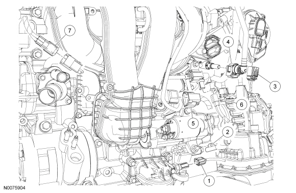
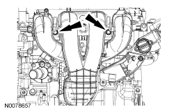
Intake Manifold (View 2 of 3)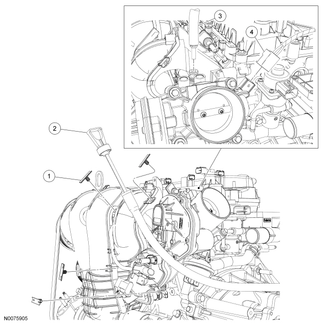
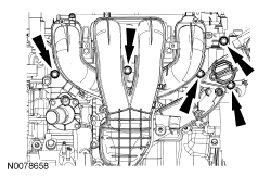
Intake Manifold (View 3 of 3)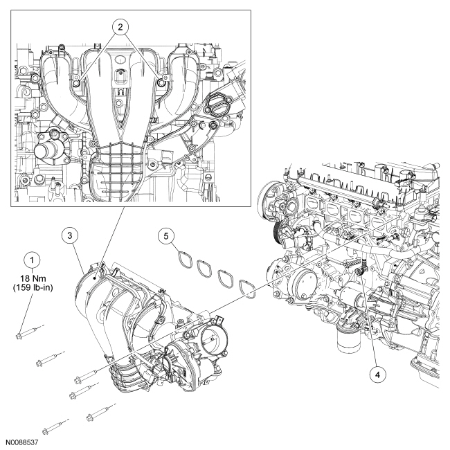
Removal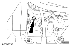
| Item | Part Number | Description |
|---|---|---|
| 1 | 14A464 | Engine Oil Pressure (EOP) switch electrical connector (part of 12C508) |
| 2 | — | Wire harness retainer (part of 12C508) |
| 3 | 14A464 | Electronic throttle control electrical connector (part of 12C508) |
| 4 | 9D289 | Fuel vapor return hose |
| 5 | 14A464 | Manifold Absolute Pressure (MAP) sensor electrical connector (part of 12C508) |
| 6 | 14A464 | Swirl control valve solenoid electrical connector (part of 12C508) (if equipped) |
| 7 | 14A624 | Knock Sensor (KS) electrical connector (part of 12C508) |
Intake Manifold (View 2 of 3)
| Item | Part Number | Description |
|---|---|---|
| 1 | 13A506 | Wire harness pin-type retainer (part of 12C508) (4 required) |
| 2 | 7A020 | Transaxle fluid indicator |
| 3 | 19D848 | Power brake booster vacuum tube |
| 4 | 14A464 | Swirl control valve sensor electrical connector (part of 12C508) (if equipped) |
Intake Manifold (View 3 of 3)
| Item | Part Number | Description |
|---|---|---|
| 1 | W500311 | Intake manifold bolt (6 required) |
| 2 | W500312 | Intake manifold bolts |
| 3 | 9424 | Intake manifold |
| 4 | 6758 | PCV hose |
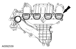
| 5 | 9439 | Intake manifold gasket |
Removal
- With vehicle in NEUTRAL, position it on a hoist. For additional information, refer to Section 100-02.
- Remove the Air Cleaner (ACL) outlet pipe. For additional information, refer to Section 303-12.
- Remove the front impact severity sensor. For additional information, refer to Section 501-20B.
- Remove the transaxle fluid indicator.
- Remove the lower intake manifold bolt.
- Remove the oil level indicator and tube. For additional information, refer to Oil Level Indicator and Tube in this section.
- Disconnect the Engine Oil Pressure (EOP) switch electrical connector and detach the wire harness retainer from the starter stud bolt.
- Disconnect the electronic throttle control electrical connector.
- Disconnect the fuel vapor return hose.
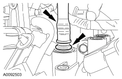
- Disconnect the power brake booster vacuum tube.
- Depress the quick release locking ring.
- Pull the vacuum tube out of the quick release fitting.
- Disconnect the Manifold Absolute Pressure (MAP) sensor electrical connector.
- Detach and disconnect the Knock Sensor (KS) electrical connector.
- If equipped, disconnect the swirl control valve solenoid electrical connector.
- If equipped, disconnect the swirl control valve sensor electrical connector.
- Detach all the wiring harness pin-type retainers from the intake manifold.
- NOTE: The 2 intake manifold bolts differ in length from rest of the bolts and also retain a crash bracket to the intake manifold. The 2 bolts are equipped with an attachment feature that allows them to be loosened but remain attached to the intake manifold. Do not attempt to remove the 2 bolts or the crash bracket from the intake manifold.
Loosen the 2 intake manifold bolts.
- Remove the 5 intake manifold bolts.
- Disconnect the PCV hose and remove the intake manifold.
- NOTICE: If the engine is repaired or replaced because of upper engine failure, typically including valve or piston damage, check the intake manifold for metal debris. If metal debris is found, install a new intake manifold. Failure to follow these instructions can result in engine damage.
Inspect and install new intake manifold gaskets if necessary.
- Position the intake manifold and connect the PCV hose.
- Attach the KS to the intake manifold and connect the KS electrical connector.
- NOTE: The 2 intake manifold bolts differ in length from rest of the bolts and also retain a crash bracket to the intake manifold. The 2 bolts are equipped with an attachment feature that allows them to be loosened but remain attached to the intake manifold. Do not attempt to remove the 2 bolts or the crash bracket from the intake manifold.
Install the intake manifold and hand-tighten the 2 intake manifold bolts.
- Install the 5 intake manifold mounting bolts.
- Tighten all 7 bolts to 18 N·m.
- Attach all the wiring harness pin-type retainers to the intake manifold.
- If equipped, connect the swirl control valve sensor electrical connector.
- If equipped, connect the swirl control valve solenoid electrical connector.
- Connect the MAP sensor electrical connector.
- Connect the power brake booster vacuum tube.
- Push the vacuum tube into the quick release fitting.
- Connect the fuel vapor return hose.
- Connect the electronic throttle control electrical connector.
- Connect the EOP switch electrical connector and attach the wire harness retainer to the starter stud bolt.
- Install the oil level indicator and tube. For additional information, refer to Oil Level Indicator and Tube in this section.
- Install the lower intake manifold bolt.
- Tighten to 18 N·m.
- Install the transaxle fluid indicator.
- Install the front impact severity sensor. For additional information, refer to Section 501-20B.
- Install the ACL outlet pipe. For additional information, refer to Section 303-12.
Test yourself
A quick Ford Focus quiz: every answer comes with an explanation and a link to the manual page.
Was this page helpful?