Use fender covers to avoid damaging painted surfaces.
To prevent damage to the cylinder head, wait until the engine coolant temperature drops below normal operating temperature before removing it.
When handling the metal gasket, be careful not to bend the gasket or damage the gasket contact surface.
To avoid damage, carefully disconnect the wiring connectors by holding the connector body.
Label all wires and hoses to avoid incorrect connection.
Turn the crankshaft pulley so that the No. 1 piston is at top dead center (TDC).
Remove the engine assembly from the vehicle. (Refer to Engine and Transaxle Assembly - "Engine and Transaxle Assembly")
Remove the transaxle assembly from the engine assembly. Automatic Transaxle (Refer to Automatic Transaxle System - "Automatic Transaxle")
Remove the drive plate. (Refer to Cylinder Block - "Drive Plate")
Remove the rear oil seal. (Refer to Cylinder Block - "Rear Oil Seal")
Install the engine on an engine stand for disassembly.
Remove the timing chain. (Refer to Valve Timing System - Timing Chain)
Remove the water pump assembly. (Refer to Cooling System - "Water Pump")
Remove the water inlet hose and thermostat assembly. (Refer to Cooling System - "Electric Thermostat (ECT)")
Remove the intake manifold. (Refer to Intake and Exhaust Systems — Intake Manifold)
Remove the A/C compressor. (Refer to Heating, Ventilation and Air Conditioning - "Compressor")
Remove the exhaust manifold. (Refer to Intake and Exhaust System - "Exhaust Manifold")
Remove the cylinder head assembly. (Refer to Cylinder Head Assembly - "Cylinder Head")
Remove the oil filter. (Refer to Lubrication System - "Engine Oil")
Remove the oil screen. (Refer to Lubrication System - "Oil Pan")
Check the connecting rod side clearance.
Check the oil clearance of the connecting rod bearing cap.
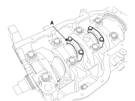
Remove the piston and connecting rod assembly.
Using a ridge reamer, remove all carbon from the upper part of the cylinder.
Remove the connecting rod bearing caps (A).
Mark the connecting rod and caps so they can be reassembled in their original position and direction.
Push the piston and connecting rod assembly with the upper bearing through the top of the cylinder block.
Keep the connecting rod and cap together with the bearings installed.
Arrange the piston and connecting rod assemblies in the correct order.
Mark the piston and connecting rod assemblies so they can be reassembled in their original positions.
Check the fit between the piston and piston pin. Try moving the piston back and forth on the piston pin. If any movement is felt, replace the piston and pin as a set.
Remove the piston rings.
Using a piston ring expander, remove the 2 compression rings.
Remove the oil control ring and coil spring by hand.
Arrange the piston rings in the correct order.
Remove the connecting rod from the piston.
Remove the snap ring (A) from the piston.
Remove the piston pin (B) from the piston.
Disassemble the piston (C) and connecting rod (D).
Inspection
Connecting Rod
Check the connecting rod side clearance. Using a feeler gauge, measure the axial play while moving the connecting rod back and forth.
A.
If out of specification, install a new connecting rod.
B.
If still out of specification, replace the crankshaft.
Connecting rod side clearance Standard: 0.10–0.25 mm (0.0039–0.0098 in.)
Check the oil clearance of the connecting rod bearing.
Make sure the alignment marks on the connecting rod and cap are aligned to ensure correct assembly.
Remove the 2 connecting rod cap bolts.
Remove the connecting rod cap and lower bearing.
Clean the connecting rod journal and bearing.
Place a piece of Plastigage on the crankshaft journal.
Install the lower bearing and cap in place and tighten the bolts. Tightening torque: Step 1: 17.7 to 22 N·m Step 2: 103 to 107°
Do not rotate the crankshaft.
Do not rotate the crankshaft.
Do not reuse the connecting rod cap bolts.
Remove the connecting rod cap and lower bearing.
Measure the width of the Plastigage at its widest point.
Oil clearance: 0.024 to 0.042 mm (0.00094 to 0.00165 in.)
If the Plastigage measurement is too wide or too narrow, remove the upper and lower bearings, then install new bearings with the same color code. Recheck the oil clearance.
Do not file, shim, or scratch the bearings or caps to adjust the clearance.
If the Plastigage indicates the clearance is still incorrect, try the next larger or smaller size bearing. Recheck the oil clearance.
If the proper clearance cannot be obtained with the appropriate larger or smaller size bearings, replace the crankshaft and repeat the inspection procedure.
If the markings are illegible due to dirt and dust buildup, do not scrape them off or use a wire brush. Clean them only with solvent or detergent.
Connecting Rod Marking Connecting Rod Specifications
Grade
Mark
Inner Diameter
0
A
48.000 to 48.006 mm (1.88976 to 1.89000 in.)
1
B
48.006 to 48.012 mm (1.89000 to 1.89023 in.)
2
C
48.012 to 48.018 mm (1.89023 to 1.89047 in.)
Crankshaft Pin Identification Mark
Stamp in the order shown by the arrow direction from #1.
Crankshaft Specifications
Grade
Mark
Pin Outside Diameter
I
1
44.966 to 44.972 mm (1.77031 to 1.77055 in.)
II
2
44.960 to 44.966 mm (1.77008 to 1.77031 in.)
III
3
44.954 to 44.960 mm (1.76984 to 1.77008 in.)
Connecting Rod Bearing Marking Connecting Rod Bearing Specifications
Grade
Mark
Bearing Thickness
A
Light Blue
1.511 to 1.514 mm (0.05949 to 0.05961 in.)
B
Black
1.508 to 1.511 mm (0.05937 to 0.05949 in.)
C
White
1.505 to 1.508 mm (0.05925 to 0.05937 in.)
D
Light Green
1.502 to 1.505 mm (0.05913 to 0.05925 in.)
E
Pink
1.499 to 1.502 mm (0.05902 to 0.05913 in.)
Select the connecting rod bearing using the selection table. Connecting Rod Bearing Selection Table
Bearing Classification Assembly
Connecting Rod Marking
0
1
2
Crankshaft Marking
I (1)
E (Pink)
D (Light Green)
C (White)
II (2)
D (Light Green)
C (White)
B (Black)
III (3)
C (White)
B (Black)
A (Blue)
Inspect the connecting rods.
When reinstalling, make sure the cylinder numbers marked on the connecting rod and cap match those noted during disassembly. When installing a new connecting rod, make sure the bearing locking tabs are on the same side.
Replace the connecting rod if it is damaged on the rod surface at either end. Also, if the steps are worn or the surface is heavily roughened, the small end inside diameter is visible, and the rod must also be replaced.
Using a connecting rod alignment tool, check the connecting rod for bend and twist. If the measured value is close to the repair limit, correct the rod with a press. Any connecting rod that is severely bent or distorted must be replaced. Connecting rod bend limit: 0.05 mm (0.0020 in.) or less per 100 mm (3.94 in.) Connecting rod twist limit: 0.10 mm (0.0039 in.) or less per 100 mm (3.94 in.)
When installing connecting rods without bearings, there should be no difference in the side surfaces.
Clean the piston.
Using a gasket scraper, remove carbon deposits from the top of the piston.
Using a ring groove cleaner or a broken piston ring, clean the piston ring grooves.
Using solvent and a brush, thoroughly clean the piston.
Do not use a wire brush.
Check the piston-to-cylinder clearance by calculating the difference between the cylinder bore inside diameter and the piston outside diameter.
Piston-to-cylinder clearance: 0.02 - 0.04 mm (0.0008 - 0.0016 in.)
Using a cylinder bore gauge, measure the cylinder bore diameter at the positions in the axial and thrust directions.
Select a piston that matches the cylinder bore size class.
Piston-to-cylinder clearance: 0.02 - 0.04 mm (0.0008 - 0.0016 in.)
Check the cylinder bore size code on the side of the cylinder block. Cylinder bore inside diameter
Size code
Cylinder Inner Diameter
A
81.00 - 81.01 mm (3.1890 - 3.1894 in.)
B
81.01 - 81.02 mm (3.1894 - 3.1898 in.)
C
81.02 - 81.03 mm (3.1898 - 3.1902 in.)
Check the piston size mark on the piston top surface. Piston outside diameter
Size code
Piston Outer Diameter
A
80.97 - 80.98 mm (3.1878 - 3.1882 in.)
B
80.98 - 80.99 mm (3.1882 - 3.1886 in.)
C
80.99 - 81.00 mm (3.1886 - 3.1890 in.)
Check the piston ring side clearance. Using a feeler gauge, measure the clearance between a new piston ring and the ring groove side wall. If the clearance is greater than the maximum, replace the piston. Piston ring side clearance [Standard] No. 1 ring: 0.040 - 0.080 mm (0.00157 - 0.00315 in.) No. 2 ring: 0.040 - 0.080 mm (0.00157 - 0.00315 in.) Oil ring: 0.020 - 0.055 mm (0.00079 - 0.00216 in.)If the clearance is greater than the maximum, replace the piston.
Inspect the piston ring end gap. To measure the piston ring end gap, insert the piston ring into the cylinder bore. Position the ring at a right angle to the cylinder wall, pressing it in carefully with the piston. Measure the gap using a feeler gauge. Piston ring end gap [Standard] No. 1 ring: 0.15 - 0.30 mm (0.0059 - 0.0118 in.) No. 2 ring: 0.30 - 0.45 mm (0.0118 - 0.0177 in.) Oil ring: 0.20 - 0.40 mm (0.0079 - 0.0157 in.)If the gap exceeds the limit, replace the piston rings. If the gap is too large, recheck the cylinder bore inside diameter. If the bore diameter exceeds the service limit, the cylinder block must be replaced.
Measure the clearance between the piston pin and the piston. Piston pin-to-piston clearance: 0.004 - 0.012 mm (0.00016 - 0.00047 in.)
Check the clearance between the piston pin outside diameter and the connecting rod small end inside diameter. Piston pin-to-connecting rod clearance: 0.007 - 0.018 mm (0.00028 - 0.00071 in.)
Piston Piston Rings Piston Pins
Installation
Thoroughly clean all parts to be assembled.
Before installing parts, apply new engine oil to all sliding and rotating surfaces.
Assemble the piston and connecting rod.
Install the snap ring (A) on one side of the piston pin hole.
Align the piston front mark with the connecting rod front mark.
Insert the piston pin (B) into the piston pin hole and the connecting rod small end hole.
After installing the piston pin, install the snap ring (C) on the other side.
Apply a sufficient amount of engine oil to the piston outer surface, the piston pin hole inner surface, and the connecting rod small end hole before installing the piston pin.
Be careful not to damage or scratch the connecting rod small end hole, piston pin hole, and piston pin when installing the piston pin.
Install the snap ring securely so that it contacts the entire piston pin hole groove.
Install the piston rings.
Install the oil ring and coil spring by hand.
Using a piston ring expander, install the 2 compression rings with the factory mark facing up.
Position the piston rings so that the ring gaps are as shown in the illustration. (No. 1 ring should be on the opposite side from the No. 2 ring.) Example)
Components 1. Piston ring 2. Snap ring 3. Piston pin 4. Piston 5. Connecting rod 6. Upper connecting rod bearing 7. Lower connecting rod bearing 8. Connecting rod bearing cap ...
Hyundai Elantra AD (2016-2020) Owner's Manual: Vehicle Stability Management (VSM) Vehicle Stability Management (VSM) is a function of the Electronic Stability Control (ESC) system. It helps maintain vehicle stability during acceleration or sudden braking on wet, slippery, or uneven roads where traction on the four tires may suddenly differ. WARNING Take t...
Hyundai Elantra AD (2016-2020) Owner's Manual: Disc Brake Wear Indicator, Rear Drum Brakes Disc Brake Wear Indicator When your brake pads are worn and new pads are needed, you will hear a high-pitched warning sound from the front or rear brakes. You may hear this sound while driving, or it may occur whenever you apply the brake pedal. Note that some driving conditions or climate...
?
Test yourself
A quick Hyundai Elantra AD quiz: every answer comes with an explanation and a link to the manual page.


 Piston and Connecting Rod Components and Component Location
 Crankshaft Components and Component Location