Engine Electrical System
Smart Cruise Control Unit Repair Procedures
In this manual: Engine Electrical System
24steps
~159min
5/5difficulty
3special tools
Done 0 of 24
Removal
- Remove the bumper. (Refer to Body – "Front Bumper")
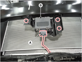
- Disconnect the Smart Cruise Control unit connector (A).
- Remove the Smart Cruise Control unit assembly (B) from the vehicle after loosening the mounting bolts.

Installation
- Install in the reverse order of removal.
- Align the Smart Cruise Control sensor. (Refer to Engine Electrical System – "Smart Cruise Control (SCC) Alignment").
- Install the bumper cover. (Refer to Body - "Front Bumper Cover")
Smart Cruise Control (SCC) Sensor Alignment
The purpose of alignment is to ensure correct SCC performance. For the sensor to operate correctly, the sensor must be properly aligned. Sensor alignment has a major effect on road evaluation, lane prediction and target processing. When the sensor is misaligned, SCC performance cannot be guaranteed. Therefore, when the sensor is reinstalled or a new sensor is installed on the vehicle, the sensor must be aligned by service personnel.
|
|

- Park the vehicle horizontally on level ground.

- The alignment may be inaccurate if the installation surface height and the vehicle and reflector tilt angles differ.
- Perform the alignment in an area with a minimum clearance of 8 m (26 ft) in front, 4 m (13 ft) to the sides, and 1.2 m (4 ft) above the vehicle.
- Remove heavy items from the vehicle interior (seating area and trunk).
- Make sure all tires are inflated to the specified pressure.
- Remove objects (metal plates, resin, etc.) that may cause electrical signal interference from the area where the sensor alignment is performed.
- Make sure the vehicle does not move or vibrate when performing sensor alignment (door open/close or entering/exiting the vehicle).
- Make sure the radiator grille and sensor cover are not contaminated.
- Make sure the wheel alignment angles are within specification.
- Do not turn off the power while performing sensor alignment.
- The voltage supplied to the radar sensor must be 9 to 16 V.
- The temperature in the area where sensor alignment is performed must be within -30 to 60 °C.

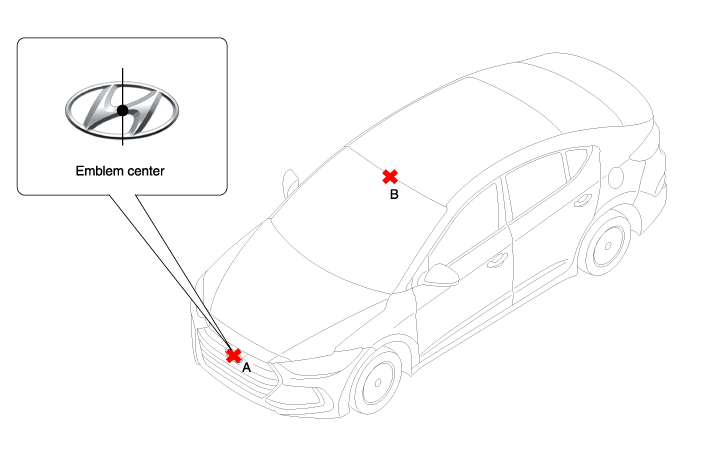
- Mark the center point of the emblem (A) and the center point at the top of the windshield (B).
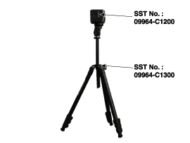
- Attach the SCC calibration laser (Part No.: 09964-C1200) to the tripod (Part No.: 09964-C1300).
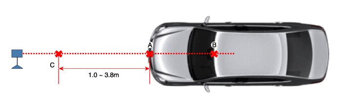
- Align the vertical laser line with (A) and (B) using the SCC calibration laser pointer.

- Mark (C) is located 1.0 to 3.8 m (3.3 to 12.5 ft) from (A) in front of the vehicle.
- Detach the SCC calibration laser (SST No.: 09964-C1200) from the tripod (SST No.: 09964-C1300).
- Align the plumb bob with point (C).
- Attach the reflector (SST No.: 09964-C1100) to the tripod (SST No.: 09964-C1300) and set the reflector center height to 344 mm (13.5 in).

- Level the reflector horizontally using the leveler built into the tripod (SST No.: 09964-C1300).
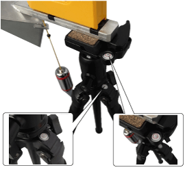
- Adjust the level so the level bubble is between the specification lines.
- Remove the plumb bob.
- Visually check that the reflective surface of the reflector is level with the front of the vehicle.
- Visually check the radar sensor and the front bumper surface again for the following items.
- Make sure there is no debris or reflective objects on the radar surface.
- Make sure there is no debris or reflective objects on the radiator grille.
- Connect GDS to the vehicle DLC and start the sensor alignment.
- Vibration with the engine running may cause inaccurate sensor alignment. Perform sensor alignment with the ignition in the IG ON position.
- After selecting the correct vehicle model, select "SCC Alignment" from the special functions in the GDS menu.

- Perform the sensor alignment by following the instructions shown on the GDS screen.

- If sensor alignment fails, check the alignment conditions. Turn the ignition off, then repeat the sensor alignment procedure.
Inspection
Smart Cruise Control System Malfunction Inspection Procedures- Check the bumper appearance and accident history. (Vehicle appearance, service history, and bumper replacement) > If the vehicle was involved in an accident, the SCC mounting part may be twisted.
- Check whether the radar sensor cover on the bumper is contaminated. > If the cover is contaminated, the SCC may be affected by foreign substances during operation.
- After starting the engine, check the SCC warning message in the cluster and the DTC. (Refer to Trouble Code Manual)
Test yourself
A quick Hyundai Elantra AD quiz: every answer comes with an explanation and a link to the manual page.
Was this page helpful?