Body Electrical System
AVN Antenna Repair Procedures
In this manual: Body Electrical System
24steps
~144min
4/5difficulty
Done 0 of 24
Inspection
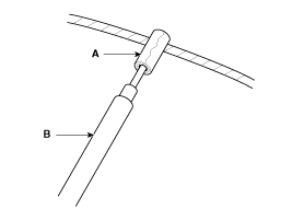
Glass Antenna Test- Wrap aluminum foil (A) around the tip of the tester probe (B), and move the probe along the grid line to check whether it is open.
- Place one end of the tester probe on the glass antenna connector (A), and move the other end along the antenna wire to check continuity.
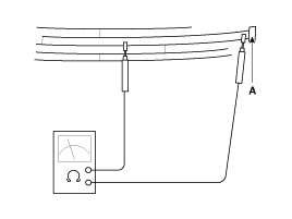
|
- Lightly rub the area around the broken section (A) with fine steel wool, then wipe with alcohol. Attach masking tape as shown below.
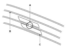
- Mix conductive paint with thinner and apply the mixture three times at 15-minute intervals.
- Before applying power, remove the masking tape. For a finished surface, remove excess paint with a knife after the paint has dried (approx. 1 day).
After completing the repair, wipe the glass with a dry soft cloth or wipe the grid line with a slightly damp cloth.
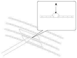
- Check the continuity of the repaired wire.
- Remove the right glass antenna from the rear quarter trim, then disconnect the power wire from the amplifier.
- Turn on the radio. Measure the voltage between terminal 2 of the power cable on the harness side (A) and body ground (B).
OK: Approximately 12 V (ACC+)

- Using the tester, measure the resistance of the AM wiring between 1 and 2.
A. AM / FM Antenna Grid Terminal B. Body ground 
- Using a tester, measure the resistance of the FM wiring between A and B.
A. FM2 antenna array terminal B. Body ground 
- Check the grid lines for continuity.
- If radio reception is poor even after checking the circuit, replace the glass antenna amplifier. If reception quality does not improve, inspect the radio cable and audio unit.
- Check continuity between the center terminals of the antenna cable.
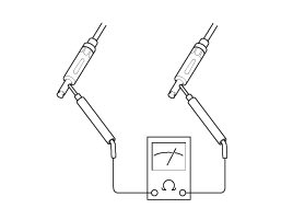
- Check continuity between the outer terminals of the antenna cable. There should be continuity.
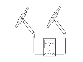
- If there is no continuity, replace the antenna cable.
- Check continuity between the center terminal (A) of the antenna cable and the glass antenna terminal (B). There should be continuity.
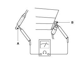
- If there is no continuity, replace the antenna amplifier.
- Check continuity between the center terminal (A) and the outer terminal (B) of the antenna cable. There should be no continuity.
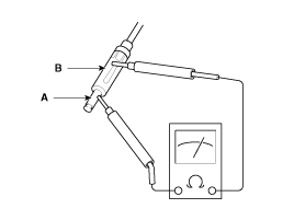
- If there is continuity, replace the antenna cable.
Removal
- Disconnect the negative (-) battery terminal.
- Remove the roof headlining. (Refer to Body - "Roof Headlining Assembly")
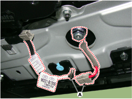
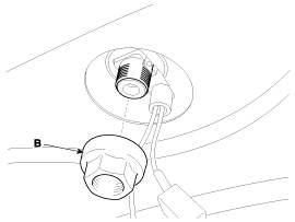
- Remove the roof antenna (A) after loosening the nut (B).
Installation
- Connect the roof antenna connectors.
- Install the rear roof garnish.
- Make sure the cables and connectors are connected correctly.
- Check the audio system.
Test yourself
A quick Hyundai Genesis DH quiz: every answer comes with an explanation and a link to the manual page.
Was this page helpful?