Drive Shaft and Axle
Front Differential Assembly (AWD) Repair Procedures
In this manual: Drive Shaft and Axle
47steps
~322min
5/5difficulty
8special tools
Done 0 of 47
Removal
- Loosen the wheel nuts slightly. Raise the vehicle and make sure it is securely supported.
- Remove the front wheel and tire (A) from the front hub.
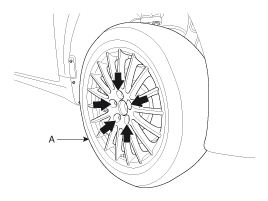
Be careful not to damage the hub bolts when removing the front wheel and tire.
- Remove the lower covers (A) and (B).
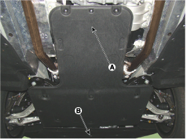
- Remove the suspension member. (Refer to Suspension System - "Suspension Member")
Using SST Engine Support, support the engine.

- Remove the front propeller shaft by loosening the bolts. [Both sides]
Tightening torque: 49.0 ~ 69 N·m
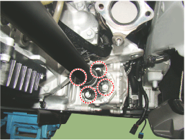

- Remove the steering gear. (Refer to Steering System - Electric Power Steering)
- Remove the front drive shaft. (Refer to Drive Shaft and Axle - Front Propeller Shaft Assembly)
- Remove the engine mount (A).

- Remove the front differential assembly.
Tightening Torque: 58.8 ~ 64 N·m

- Install in the reverse order of removal.
Disassembly
[Differential Case Assembly]- Drain the oil by removing the drain plug (A).
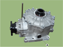
Use a new gasket (A) when reinstalling the drain plug. - Place the front differential assembly on SST (09474-4E400).

- Remove the side seal (A) using a screwdriver.
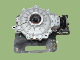
- Loosen the bolts and remove the cover (B) from the differential case.

- Using a hammer and chisel, remove the spacer (A) and side bearing race (B).
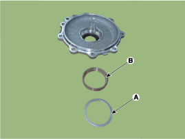
- Separate the differential case assembly from the differential carrier.
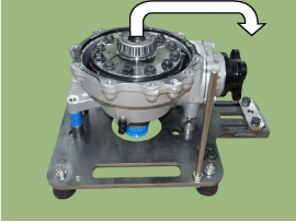

- Remove the seal (A) from the differential carrier.
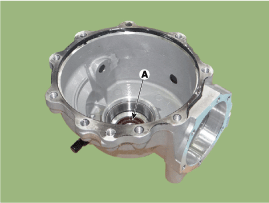
- Using SST (09452-2W300), remove the shim and bearing race from the differential carrier.

- Using SST (09474-4E200), remove the side bearing.
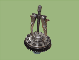
Use a new bearing when reinstalling. Aerosol lubricant can be used to make bearing removal easier. - Loosen the bolts and remove the differential carrier (A) and ring gear (B).
Make alignment marks on the gear carrier and ring gear.
- Remove the pinion bearing race.
- Using SST (09474-4E400), position the front differential carrier.
- Loosen the lock nut and remove the companion flange (A).
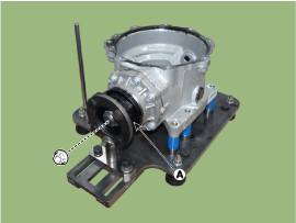
- Loosen the bolts and remove the pinion bearing race.
Tightening torque: 34.3 ~ 37 N·m

- Remove the drive pinion assembly using a press.
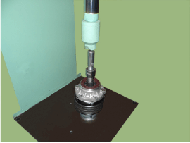
- Remove the pinion seal (A) and front pinion bearing from the bearing race using a screwdriver.

- Using a hammer and chisel, remove the front pinion bearing race (A).

- Separate the pinion bearing spacer.

- Using a press, remove the pinion rear bearing.

Inspection
- After cleaning, inspect the parts for damage or wear. If any is found, follow the method below.
Item Identify Gear Set (Drive Pinion and Ring Gear) Replace the gear set with a new one if the gear teeth are damaged (cracks/pits/dents). Bearing Replace the bearing with a new one if the roller or race is damaged (cracks/pits/dents). Seal Replace the seal with a new one whenever the differential is disassembled. Differential Case Replace the carrier with a new one if the inside bearing support is damaged (cracks/pits/dents) or if a crack is found on the inside or outside. Companion Flange Replace the pinion seal with a new one if the contact surface is damaged (cracks/pits/dents). Open Type Differential Gear Set
(Differential Side Gear and Differential Pinion Gear)Replace the gear set with a new one if the gear tooth or tooth surface is damaged (cracks/pits/dents). Differential Washer
(Differential Side Gear Washer and Differential Pinion Gear Washer)Replace the washer with a new one if its surface is damaged (cracks/pits/dents).
Installation
|
- Using a round pipe (A), press in the pinion rear bearing (B).
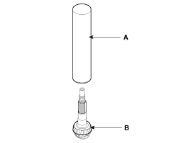
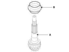
Do not reuse the bearing. Be sure to install a new one. - Install the pinion bearing spacer (B) onto the drive pinion (A).
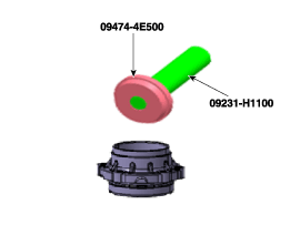
Do not reuse the spacer. Be sure to install a new one. - Using SST (09452-4E500), install the pinion front bearing race.
Do not reuse the race. Be sure to install a new one. - Using SST (09432-33700), install the pinion rear bearing race.

Do not reuse the race. Be sure to install a new one. - After installing the pinion seal, install the drive pinion assembly onto the pinion carrier.

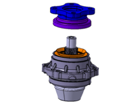
Do not reuse the seal. Be sure to install a new one. - Install the companion flange.
- Tighten the pinion lock nut. Pinion bearing preload: 0.9 to 1.8 N·m
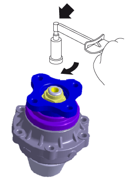
Maintain a constant rotation speed (60 rpm). - Install the pinion O-ring.
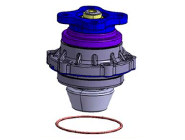
Do not reuse the O-ring. Be sure to install a new one. Apply a small amount of oil along the O-ring. - Install the gear assembly
Tightening torque: 34.3 ~ 37 N·m
- Install the differential carrier and ring gear.
Tightening torque: 78.4 ~ 88 N·m
Tighten the bolts in a diagonal sequence. - Using SST (09432-3D500), install the side bearing.

Do not reuse the bearing. Be sure to install a new one. - Using SST (09474-4E100), install the differential case oil seal.
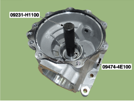
Do not reuse the seal. Be sure to install a new one. - Using SST (09432-3D900), install the shim and perform a race on the differential carrier.

Do not reuse the race. Be sure to install a new one. - Using SST (09432-3D900), install the shim and burnish the differential case cover.

- Install the differential case assembly onto the differential carrier.

- Check the backlash on the companion flange. Backlash: Standard: 0.07~0.15 mm (0.003~0.006 in) Companion flange PCD equivalent: 0.11~0.23 mm (0.004~0.009 in) Standard companion flange turning torque: 30 kgf·cm
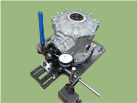
Measure the backlash by applying a turning torque of 30 kgf·cm to the companion flange in both directions. Adjust the thickness of both shims. Disassemble again when the backlash is greater or less than the specification. When the backlash is greater than the specification, increase the cover-side shim thickness by one unit and decrease the carrier-side shim thickness by one unit. When the backlash is less than the specification, increase the carrier-side shim thickness by one unit and decrease the cover-side shim thickness by one unit. Shim adjustment unit: 0.03 mm. Inner bearing adjusting shimPart No. Thickness (mm) 47464-4F200 2 47464-4F203 2.03 47464-4F206 2.06 47464-4F209 2.09 47464-4F212 2.12 47464-4F215 2,15 47464-4F218 2.18 47464-4F221 2.21 47464-4F224 2,24 47464-4F227 2,27 47464-4F230 2.3 47464-4F233 2,33 47464-4F236 2,36 47464-4F239 2,39 47464-4F242 2,42 47464-4F245 2,45 47464-4F248 2,48 47464-4F251 2,51 47464-4F254 2,54 47464-4F257 2,57 47464-4F260 2,6 47464-4F263 2,63 47464-4F266 2,66 47464-4F269 2,69 47464-4F272 2,72 47464-4F275 2,75 47464-4F278 2,78 47464-4F281 2,81 47464-4F284 2,84 47464-4F287 2,87 47464-4F290 2,9 47464-4F293 2,93 47464-4F296 2,96 47464-4F299 2,99 47464-4F302 3.02 47464-4F305 3,05 47464-4F308 3.08 47464-4F311 3.11 Tooth Contact Solution Standard Contact
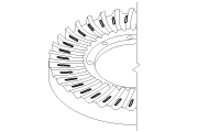
1. Heel Contact 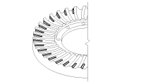
Increase the thickness of the pinion height adjusting shim to move the drive pinion closer to the ring gear.
Also, to adjust the backlash, move the ring gear farther away from the drive pinion.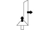
2. Face Contact 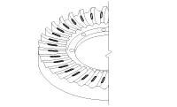
3. Toe Contact 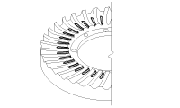
Decrease the thickness of the pinion height adjusting shim to move the drive pinion farther from the ring gear.
Also, to adjust the backlash, move the ring gear closer to the drive pinion.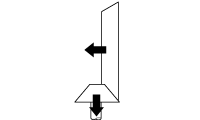
4. Flank Contact 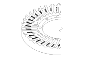
- The tooth contact pattern is a method of evaluating the results of pinion height and final gear backlash adjustment. Repeat the pinion height and final gear backlash adjustments until the tooth contact pattern matches the standard tooth contact pattern.
- If the correct pattern cannot be obtained, the drive pinion and ring gear have exceeded their limits. Both gears must be replaced as a set.
- Install the differential carrier cover, then install the oil seal. Tightening torque: 39.2 ~ 49 N·m Sealant: LIQUID GASKET or equivalent LT5702

- Remove all old sealant before applying.
- Remove the old sealant from the surface and evenly apply sealant in a 2-3 mm bead to the rear cover surface.
- Measure the total preload. Total preload: Drive pinion bearing preload (9.2~18.3 kgf·cm) + (10~40 kgf·cm) / Final gear ratio

Maintain a constant rotation speed (60 rpm). - Install the drain plug (A).
Tightening Torque: 49.0 ~ 69 N·m
Do not reuse the drain plug. Always install a new one. - Install the rear differential assembly onto the vehicle. Loosen the filler plug (A) and fill with oil.
Tightening torque: 44.1 ~ 54 N·m
Oil type (~2015.02.28): Hypoid gear oil MS517-15 GT 75W/90 (GL-5) (SHELL HD AXLE OIL 75W90) or equivalent SK HK G-5 75W90. Oil capacity (L): 0.7 ± 0.05. Oil type (2015.03.01~): Hypoid gear oil MS517-15 GT 75W/85 (GL-5) (equivalent SK HK SYN GEAR OIL 75W/85). Oil capacity (L): 0.7 ± 0.05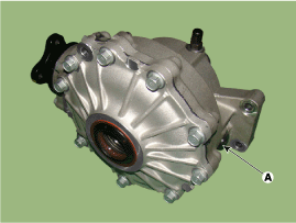
Test yourself
A quick Hyundai Genesis DH quiz: every answer comes with an explanation and a link to the manual page.
Was this page helpful?