Body Electrical System
Front Wiper Motor Repair Procedures
In this manual: Body Electrical System
18steps
~108min
4/5difficulty
Done 0 of 18
Removal
- Disconnect the negative (-) battery terminal.
- Remove the wiper arm (A) and blade by loosening the nut.
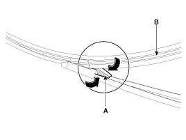
- If necessary to remove the wiper blade, press both sides of the wiper blade latch (A), then remove the wiper blade.
- Remove the upper hood cover. (Refer to Body - "Upper Cover Panel")
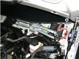
- Disconnect the wiper motor connector (A) from the wiper motor and linkage assembly.
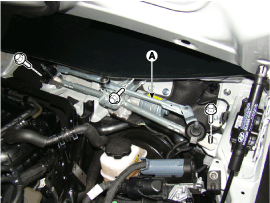
- Remove the windshield wiper motor and linkage assembly (A) by removing the 3 bolts.
- While holding the wiper motor crank, remove the upper link (A) from the wiper motor crank.
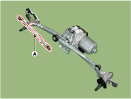
Before removing the wiper motor and linkage, make sure the motor stops at the automatic stop position. Before removing the wiper motor and linkage assembly, check the location and installation angle of the wiper motor crank and linkage.
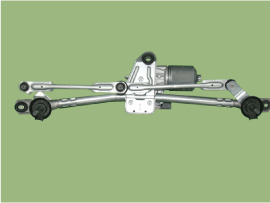
- Remove the lower link (A) from the wiper motor crank.
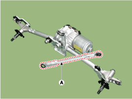
Before removing the wiper motor and linkage assembly, check the location and installation angle of the wiper motor crank and linkage. - Remove the crank (B) after loosening the nut (A).
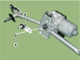
- Remove the bracket (A) and motor (B) after loosening the screws (3EA).
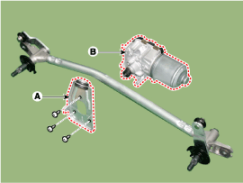
Installation
- Install the wiper motor and linkage assembly, then connect the wiper motor connector.
Tightening torque: 6.9~10.8 N·m
- Install the hood upper cover.
- Install the windshield wiper arm and blade.
Tightening torque: 22.5~26 N·m

- Turn the wiper motor to make sure it is in the park position. If necessary, adjust the wiper arm and blade.
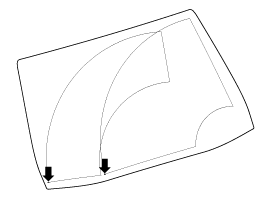
- Install the wiper arm and blade to the specified position. A: Automatic stop position (blade)
Inspection
- The body wire harness system can quickly check faulty parts using the vehicle scan tool (GDS). The GDS provides the following information.
- Self-Diagnosis: Malfunction and Code Number Check (DCT)
- Current Data: Check the system input/output status.
- Actuation Test: Check the system operating status
- Additional Functions: Controls other functions, including system parameter setting and zero point adjustment.
- Select "Vehicle Model" and the system to be checked to inspect the vehicle with the tester.
- After selecting BCM, select the module to check.
Select "BCM" and "Instrument Panel Module (IPM)" to check the instrument panel module (IPM). - Select the Current Data menu to check the current input/output status. The input/output data for sensors related to the Instrument Panel Module (IPM) can be checked.
Test yourself
A quick Hyundai Genesis DH quiz: every answer comes with an explanation and a link to the manual page.
Was this page helpful?