Body Electrical System
Relay Box (Interior) Description and Operation
In this manual: Body Electrical System
6steps
~36min
2/5difficulty
Done 0 of 6
Description
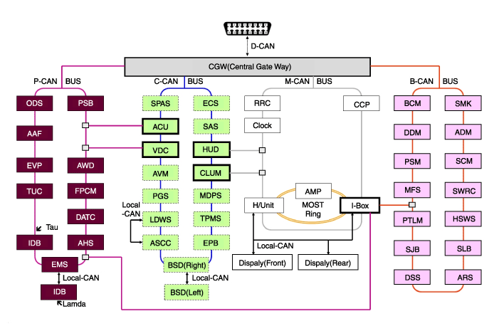
| Item | Description |
| AAF | Active Air Flap |
| ACU | Airbag Control Unit |
| ADM | Assist Door Module |
| AHD | Active Hood System |
| AMP | Amplifier |
| ARS | Armrest Switch |
| ASCC | Advanced Smart Cruise Control |
| AVM | Around View Monitor |
| All-wheel drive | All-Wheel Drive |
| B_CAN | Body Controller Network |
| BCM | Body Control Module |
| BSD | Blind Spot Detection |
| C_CAN | Chassis Controller Area Network |
| CPK | Center Control Panel |
| KLUM | Cluster Module |
| DATC | Dual Automatic Temperature Control |
| DDM | Driver door module |
| Display | Display Monitor |
| DSS | Driver Seat Switch |
| ECS | Electronic Control Suspension |
| Emergency Call | Engine Control System |
| EPB | Electronic Parking Brake (EPB) |
| EVP | Electric Vacuum Pump (EVP) |
| FPCM | Fuel Pump Control Module |
| ea. | Head unit |
| HSWS | Tactile Steering Warning |
| HUD | Projection Display |
| I-BOX | Telematics System |
| IBR | Integrated Dynamic Brake |
| LDWS | Lane Departure Warning System |
| M_CAN | Multimedia Controller Network |
| MDPS | Motor Driven Power Steering |
| MFS | Multifunction switch |
| ORV | Passenger Sensing System |
| P_CAN | Power Train Controller Area Network |
| PGS | Park Assist System |
| PSB | Pre-Safe Belt |
| PSM | Power Seat Module |
| PTLM | Power Liftgate Module |
| RKR | Rear Remote Control |
| CAC | Steering Wheel Angle Sensor |
| SKM | Steering Column Module |
| SJB | Smart Junction Box |
| SLB | Lumbar Seat |
| SMK | Smart Key Unit |
| SPAS | Smart Parking Assist System (SPAS) |
| SWRC | Steering Wheel Remote Control |
| TCU | Transmission Control Unit |
| SCP | Tire Pressure Monitoring System |
| VDC | Vehicle Dynamic Control |
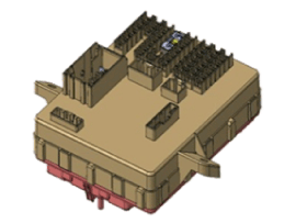
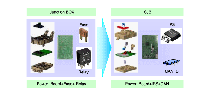
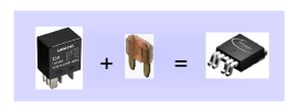
IGPM (Central Gateway and Intelligent Junction Block) The IGPM (Integrated Gateway Power Management module) is an integrated model of the smart junction block and central gateway. It performs the function of a conventional "Smart Junction Block" and the communication function of the "Central Gateway".
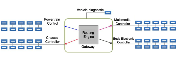
- CGW Main Specifications
- Routing: Exchanging information between different vehicle communication networks.
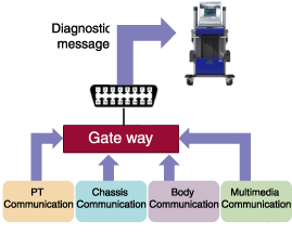
- Network security control: allows only communication check (D-CAN) for connecting the vehicle communication network in order to prevent
- Additional Functions
A. If the warning lamp is on, perform remote diagnosis of the chassis system (C-CAN) via the I-Box and gateway.
The I-Box remote diagnosis function (C-CAN) via the gateway must be suspended.
B. Dark Current Measurement: After sending a forced electronic shutdown message for each network from the diagnostic equipment, the gateway also enters sleep mode. C. Operating Current Check: Check the operation of the electronic components. - Diagnosis of CAN communication failure due to a communication controller defect (the CGW records a DTC for the controller with the transmission error).
- Routing: Exchanging information between different vehicle communication networks.
- How to Check the CGW
- Although the "No CGW CAN Signal (TIMEOUT)" record appears when checking the trouble code of a faulty electronic component, never determine it as a CGW failure. The CGW is the controller that serves as an intermediary between the transmitting and receiving controllers in the vehicle. If one of the following two cases occurs: (1) the transmitting controller cannot send a message to the CGW, so the CGW cannot send it to the receiving controller; (2) the CGW sends a predefined value (Timeout Value), and the receiving controller records a trouble code for message transmission failure. Therefore, to finally identify the controller that cannot send the CAN signal, the CGW DTC must be checked. The CGW records a DTC only if it fails to receive a signal for more than 10 seconds after KEY ON. To determine the cause of the absence of CAN signal transmission, the CGW trouble code must be checked after waiting more than 20 seconds after KEY ON.
- If the CAN communication control unit is not reinstalled after removal from the vehicle, the CGW records the "No CAN Signal" trouble code for the device.
If the trouble code remains after replacing the electronic components and the trouble code is not erased, check whether the connector is damaged, whether the electronic component is properly connected, and whether the controller CAN wiring operates normally. If the remote electronic component cannot be reinstalled, the "Erase Expected Network Configuration" service must be performed. Refer to the DTC inspection manual for the execution method of each trouble code service. Otherwise, the "No CAN Signal" DTC on the corresponding controller cannot be erased.
For example, the trouble code "DDM CAN signal is not out" is generated when the remote DDM module is not reinstalled.
Perform "Additional Function" > "Network Setting Initialization" when checking the device (GDS), referring to the trouble code manual. - IGN2 SJB is on when the MCU has failed (a condition of malfunction due to external physical or electrical impact). Driver safety is ensured by forcibly turning on the low beam headlamps and the external and internal tail lamps when the low beam headlamp switch is ON.
- IGN2 is on when data transmission/reception is impossible due to a failure in the CAN communication line (both wires shorted high/low, BAT shorted high/low, GND shorted high/low). In case of a failure in the CAN communication line connected to the SJB module, when the low beam headlamp switch is on, the low beam headlamps and internal/external tail lamps are forcibly illuminated.
|
- Switch Signal Input
- Auxiliary Seat Belt Switch, Unfastened Seat Belt Reminder Switch, Door Assist Switch, Driver Seat Belt Switch, Driver Seat Belt Switch, Rear Left Seat Door Switch, Rear Right Seat Door Switch, Rear Left Seat Belt Switch, Rear Right Seat Belt Switch, Rear Center Seat Belt Switch, IGN1 Switch, IGN2 Switch, Brake Fluid Sensor, Trunk Opening Switch, Trunk Lid Handle Switch, HID Headlamp (Option), HID Headlamp Option, ADV Emergency Switch, Low Beam Headlamp Switch, Hood Switch, Dark Switch, Left Front/Rear Turn Signal Switch, Right Front/Rear Turn Signal Switch
- IPS & ARISU Low Beam Left Headlamp, Low Beam Right Headlamp, High Beam Right Headlamp, High Beam Right Headlamp, Front Left/Right Fog Lamp, License Plate Lamp, Outer Left Rear Lamp, Outer Rear Lamp, Left Front/Rear Turn Signal, Right Front/Rear Turn Signal, Static Cornering Left Lamp, Static Cornering Right Lamp, DRL, Left DRL Lamp, Right DRL Lamp, Trunk Lamp, Body Resistance, Cut Detection, Front Left Turn Signal Output, Front Right Turn Signal Output
- Relay Control: Rear Window Defroster Relay, Anti-Theft Alarm Horn Relay, Trunk Lid Relay, Room Lamp Relay, Windshield Defroster Relay, Rear Fog Lamp Relay, High Beam Headlamp Relay
- SJB Protection
- PCL (Programmable Current Limiter) Functions
A. The PCL replaces the function of the wire protection junction box. B. Operation: If the lamp current exceeds the standard level, cut off the current to protect the lamp. C. Lamp shut-off time: 300 ms or less. D. Applicable components: All lamp components are monitored by the SJB. E. Output a fault code according to the fault detection conditions. - OCL (Open Current Limit)
A. The OCL detects the open lamp condition and informs the user of it. B. Operation: Determine the lamp current and, if it is below the standard level, change the lamp operating mode. C. Applicable components: 4 turn signal lamps D. Output a fault code according to the fault detection conditions.
- PCL (Programmable Current Limiter) Functions
- SJB Fail-Safe Function
- When the MCU has failed (not operating due to external physical or electrical shock), and the IGN2 and low beam headlamp switch is ON, the SJB forcibly turns on the low beam headlamps and external/internal lamps to ensure driver safety.
- If data transmission/reception fails due to a CAN communication line fault connected to the SJB module (both High and Low lines open, High/Low BAT short, High/Low GND short), the headlamp low beam and the interior/exterior rear lamps are forced ON when IGN2 is on and the headlamp low beam switch is ON.
- Battery Saver Auto Shut-Off System
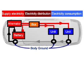
- Description: Automatically cuts off power supplied to components to reduce unnecessary dark current depending on the vehicle condition.
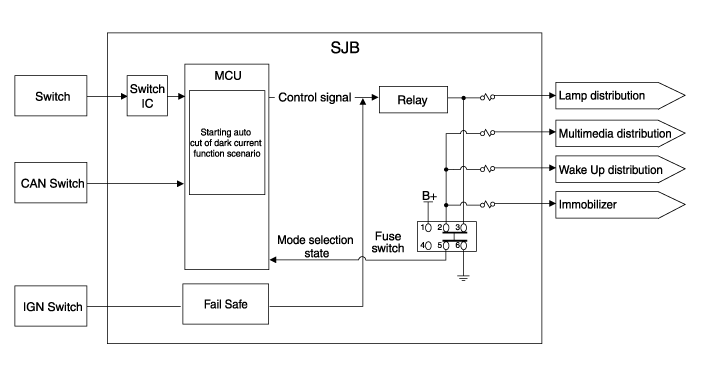
- The SJB has 3 modes: "Normal Mode", "Sleep Mode", and "Power Off Mode". The automatic dark current cut-off control is performed in "Sleep Mode".
A. "Sleep" condition: IG OFF, no constant input switch, CAN network not active. B. Sleep cancellation conditions: any input switch, CAN network activation, KEY ON, IGN ON. C. "Power Off" condition: the timer set for cutting off the load power has expired. D. "Normal Mode": The SJB function is normally active. E. "Sleep Mode": This is a low power consumption mode that is activated to reduce the power consumption of the SJB or IPM. The automatic dark current cut-off function is activated. F. "Power Off Mode": Power to the MCU and the circuit is cut off to minimize power consumption. Operation stops. - Description - Automatic Dark Current Cut-off
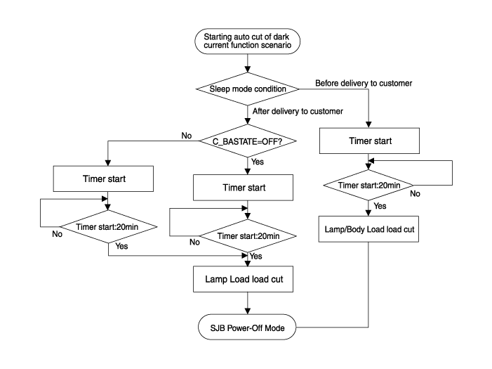
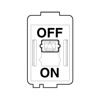
Before Delivery to Customer Fuse switch OFF. - All doors closed and door lock RKE or constant switch status (Automatic dark current cut-off scenario starts.)
- After the "sleep" state, the state lasts 20 min.
- SJB power down (SJB dark current: 200 µA) and lamp load/body load power off/wake-up
After Delivery to Customer Fuse switch ON. - All doors closed and constant switch status: C_BAState=OFF (Automatic dark current cut-off scenario starts.)
- After the "sleep" state, the state lasts 20 min.
- SJB power down (SJB dark current: 200 µA) and lamp load power off
- In case of RKE door lock: C_BAState=ON & Trunk SW=CLOSE (Automatic dark current cut-off scenario starts.)
- After "Sleep" condition for 35–65 s (waiting time for other device: 30–60 s + SJB sleep counted as 5 s).
- SJB power down (SJB dark current: 200 µA) and lamp load power cut
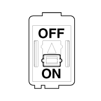
- Problem when the fuse switch is incorrectly set: If the fuse switch is set to OFF (before delivery to the customer) by the customer or a technician and the automatic dark current cut-off function is activated, the following problems may occur
Symptom Related Part - Door lock/unlock and trunk opening by RKE are not activated. (Wake-up of each module is not activated.)
BCM - Digital clock is reset. (Memory is reset.)
Digital Clock - Audio settings values (volume, frequency) are reset. (Memory is cleared.)
Audio
* If the fuse switch is turned OFF (before delivery to the customer), power to the BCM, digital clock and audio is cut off.
- Description: Automatically cuts off power supplied to components to reduce unnecessary dark current depending on the vehicle condition.
Test yourself
A quick Hyundai Genesis DH quiz: every answer comes with an explanation and a link to the manual page.
Was this page helpful?