Body Electrical System
Description and Operation
In this manual: Body Electrical System
23steps
~138min
4/5difficulty
Done 0 of 23
General Description, Installation
PAS (Parking Assist System) is an electronic driver assistance device. It encourages the driver to be cautious when parking or driving slowly after detecting an object at the side and rear of the vehicle using ultrasonic waves. PAS includes four PS sensors that detect obstacles and transmit the result, divided into three alert levels (first, second and third), to the BCM via the communication line. The BCM determines the alert level based on the communication message transmitted from the slave sensors, then activates the buzzer sound or transmits data for display.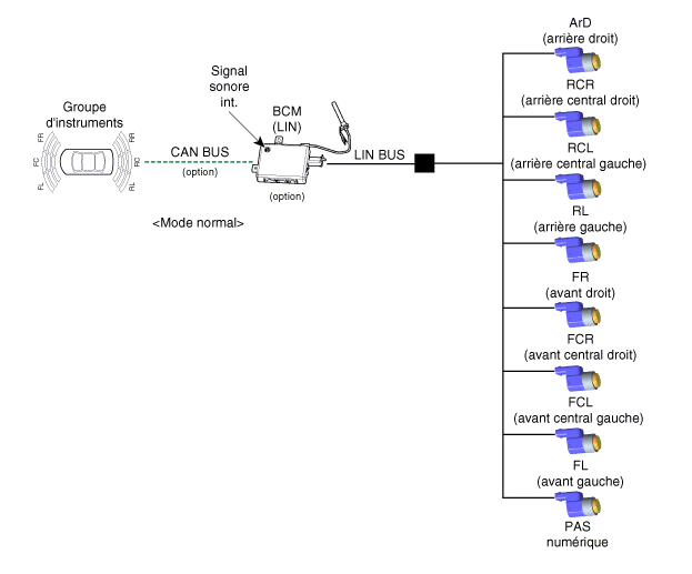
- INITIAL Mode
- System initialization time is 500 ms after ALL1 ON with the shift lever in R.
- The PAS recognizes the COVER and sets the sensor ID during initialization.
- The PAS activates each sensor, then performs diagnosis once. BCM initialization is complete.
- The PAS start buzzer operates normally when the sensor does not send an error message, and at the end of error diagnosis.
- If an error is received from the sensors, the PAS start buzzer does not operate, but the malfunction signal is output for a certain time. If there is a display option, the warning signal is also shown above.
- The buzzer sounds once when a sensor malfunctions, but the display remains illuminated continuously until the malfunction is fully repaired.
- NORMAL MODE
- LIN communication starts and is maintained after ALL1 ON with the shift lever in R.
- The BCM sends a request message to each sensor to check the initial system status, and the four sensors respond in time. At this time, if there are no problems, the alarm starts 500 ms after the shift lever is moved to R, at 300 ms intervals.
- After initialization, normal mode starts 100 ms after the end of the alarm output.
- The obstacle alarm is divided into 3 levels. The first and second levels sound intermittently, and the third level sounds continuously.
- For display, data from each sensor is sent from the BCM to the display, such as the instrument cluster. CAN communication is used for transmission, and the maximum gate time is 50 ms.
- The effective vehicle speed for PAS operation is less than 10 km/h.
- Refer to the "Digital PAS Project LIN Communication" section for more detailed communication specifications.
- SETUP MODE
- Normally, the initial condition is the same as NORMAL MODE. Use the SETUP TOOL as the master tool instead of the BCM MASTER TOOL.
- Therefore, the BCM is not connected to the LIN BUS.
- The SETUP TOOL displays the analog path after obtaining the initial data in LIN diagnostic base format by communicating with the sensors.
- Refer to the "Digital PAS Project LIN Communication" section for more detailed communication specifications.
- TUNING MODE
- The role of SETUP MODE is as follows.
- Check the assigned ID for each sensor
- Check the variant ID for each sensor.
- Normally, the initial condition is the same as NORMAL MODE. Use the SETUP TOOL as the master tool instead of the BCM MASTER TOOL.
- Therefore, the BCM is not connected to the LIN BUS.
- The SETUP TOOL checks and assigns the supplier ID and function ID.
- Refer to the "Digital PAS Project LIN Communication" section for more detailed communication specifications.
- The role of SETUP MODE is as follows.
- Measurement conditions: PVC pole (diameter 75 mm, length 1 m), normal temperature.
- Objects detected within the distance range (measured directly in front of the sensor): 61 cm (24.0 in) - 100 cm (39.4 in): ±15 cm (5.9 in); 31 cm (12.2 in) - 60 cm (23.6 in): ±10 cm (3.9 in); within 30 cm (11.8 in): ±10 cm (3.9 in).


Direct measurement
Both transmission and reception are performed by the sensor (RL, RCL, RCR, RR during operation of each sensor).
Indirect measurement
(RCL → RL, RCL → RCR, RCR → RCL, RCR → RR are performed in order.) With two or three sensors, one of them sends a transmission while the others receive a reply.
Direct and indirect measurement at the same time.
With two or three sensors, one sensor performs transmission and reception, and the others only perform reception.
- Display/buzzer information processing method of the BCM sensor: When information is received from the RL/RR sensors, the BCM directly processes each sensor's information related to the display function and buzzer output. For buzzer output from the CL/CR sensors, the BCM processes the central combination information, giving priority to both sensors. Otherwise, when information is received from faulty display units, the BCM sends each sensor's information to the instrument cluster.


- Sensor with lower priority disabled: α = 0 ms
- Sensor with lower priority is the 1st level warning: α < 340 ms
- Sensor with lower priority is the 2nd level warning: α < 170 ms
- Sensor with lower priority is the 1st level warning: β = 1700 ms
- Sensor with lower priority is the 2nd level warning: β = 1700 ms
- Sensor with lower priority is the 3rd level warning: β = 700 ms
- First warning zone (61 cm to 100 cm)

- Second warning zone (31 cm to 60 cm)

- Third warning zone (less than 30 cm)

- Malfunction signal period
- With visible display


- With visible display
- It shows only the obstacle detection position.
- At the third level alarm, the indicator flashes at one-second intervals.
- During normal alarm level display, the RCR/RCL indicator illuminates. Combined by priority.
LIN BUS error case disabled
| SECTION | Error confirmation condition | Error suppression condition |
| Initial routine | LIN BUS OFF detected once | Error is not suppressed in initial mode. |
| Normal routine | LIN BUS OFF is detected a specified number of times in succession | The malfunction is cleared when the BCM or LIN master detects that the LIN bus is on four times in succession in normal mode. |
※ Note:
- When counting errors, the output message or signal must be transmitted as the last valid value.
- Error in initial mode: the malfunction buzzer (BCM) operates with the default display (instrument cluster).
- Error in normal mode: the malfunction is displayed only on the instrument cluster, without buzzer.
Sensor error (LIN message: 0x08)
| SECTION | Error confirmation condition | Error suppression condition |
| Initial routine | Single detection of sensor malfunction message | Error is not suppressed in initial mode. |
| Normal routine | Detection of sensor malfunction message four times in succession | The malfunction is cleared when the BCM or LIN master detects that the LIN bus is on four times in succession in normal mode. |
※ On the malfunction display, the RCR/RCL indicator is displayed separately. ※ Note:
- When counting errors, the output message or signal must be transmitted as the last valid value.
- Error in initial mode: the malfunction buzzer (BCM) operates with the default display (instrument cluster).
- Error in normal mode: the malfunction is displayed only on the instrument cluster, without buzzer.
- When an error appears in the transfer state, the sensors send the same error state for the indirect condition.

Test yourself
A quick Hyundai i20 quiz: every answer comes with an explanation and a link to the manual page.
Was this page helpful?