Blind-Spot Collision Warning (BCW) Unit Repair Procedures
In this manual: Body Electrical System
25steps
~180min
5/5difficulty
6special tools
Tightening torque found on this page
Done 0 of 25
Removal
Disconnect the negative (-) battery terminal.
Remove the rear bumper. (Refer to Body - "Rear Bumper")
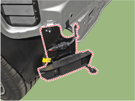
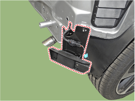
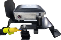
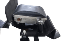
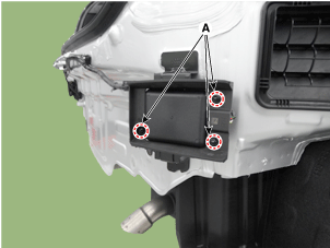
Remove the BCW unit after loosening the mounting nuts. [LH][RH]
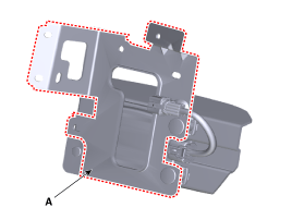
Replace the bracket (A) if the bracket is physically damaged or replaced.
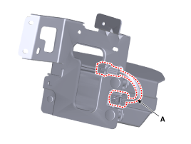
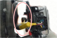
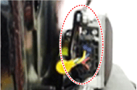
Replace the extension wiring (A) if it is damaged.
Installation
Install the BSD unit and bracket. Tightening Torque: BCW Bracket: 3.9 – 5.9 N·m BCW Unit: 3.92 ± 0.1 N·m
Install the rear bumper.
Connect the negative (-) battery terminal.
Inspection
Adjustment Overview: When replacing the BCW bracket or BCW components after a rear or side impact to a vehicle equipped with the BCW system, check the BCW angle. Inspection Before Adjustment
If DTC [C2702 (Master)] or [C2703 (Slave)] is displayed, check the following before performing adjustment.
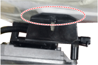
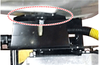
Check the vehicle condition and whether the BCW unit or bracket is deformed (installation angle, bent vehicle body, etc.).
Vehicle Inspection
Normal
Abnormal (deformation of the bracket or bolted connection)
Vehicle Inspection
Normal
Abnormal (deformation of the bracket or bolted connection)
Check the nut tightening. Check for foreign objects.
Vehicle Inspection
Normal
Abnormal (deformation of the bracket or bolted connection)
After replacing the BCW unit or bracket with the bumper removed, use the BCW unit adjustment tool kit (Special Service Tool: 09985-3T500) to perform angle adjustment.
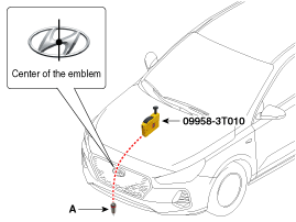
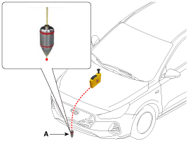
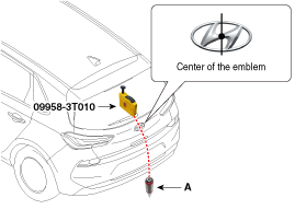
Attach the vertical plumb bob (Special Service Tool: 09958-3T010) to the hood and lower the plumb bob (A) to the ground so that it passes through the center of the emblem.
Mark the center point under the plumb bob (A).
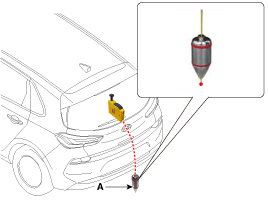
Attach the vertical plumb bob (Special Service Tool: 09958-3T010) to the luggage compartment (or liftgate). and lower the plumb bob (A) to the ground so that it passes through the center of the emblem.
Mark the center point under the plumb bob (A).
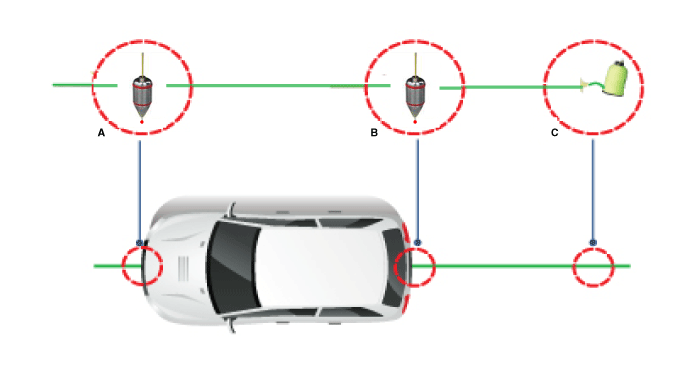
Mark the vehicle centerline with a string.
Run the string under the vehicle from the rear to the front and attach the string to the center point (A) at the front of the vehicle.
Secure the string at point (C), approximately 1.5 – 2 m from the rear of the vehicle, so that it passes through the rear center point (B).
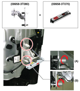
Install the BCW unit fixing adapter (Special Service Tool: 09958-3T080) on the BCW unit and mount the laser level (Special Service Tool: 09958-3T070).
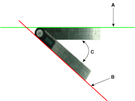
Measure the angle (C) between the centerline (A) of the measuring angle plate and the horizontal laser beam (B) using the digital protractor (Special Service Tool: 09958-3T090).
Horizontal Angle (C): 54° ± 3°
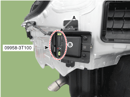
Use the digital inclinometer (Special Service Tool: 09958-3T100) to measure the vertical angle of the BCW unit.
Vertical Angle: 87° (-0.75°/+1.25°)
Measure the horizontal and vertical angles of the left and right BCW units. If the measured values deviate from the specified values, insert a shim between the BCW unit bracket. Specifications: Horizontal Angle: 54° ± 3° Vertical Angle: 87° (-0.75°/+1.25°)
After inspecting and adjusting the BCW unit angle, perform the BCW Radar Calibration Procedure.
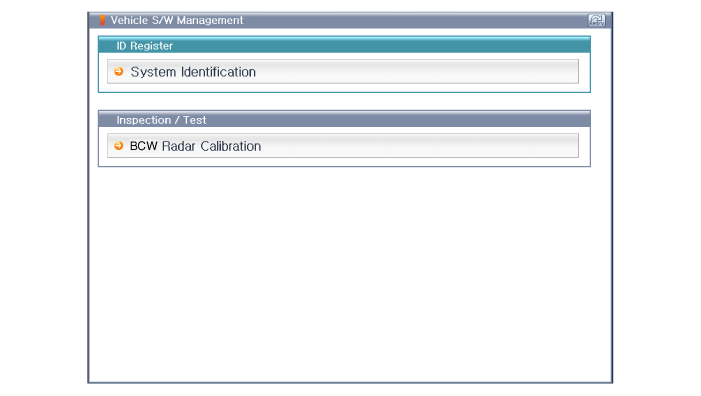
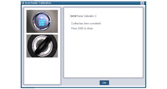
For vehicles with a rear bumper replaced in an accident, and vehicles where the BCW units have been replaced, perform BCW unit alignment using GDS.
Select the "BCW Radar Calibration" procedure in the BCW system.
Perform the "BCW Radar Calibration" procedure according to the GDS screen message.
BCW Angle Adjustment / BCW Unit Alignment
?
Test yourself
A quick Hyundai Kona quiz: every answer comes with an explanation and a link to the manual page.