Body Electrical System
Windshield Wiper and Washer Switch Repair Procedures
In this manual: Body Electrical System
15steps
~90min
4/5difficulty
Done 0 of 15
Removal
- Disconnect the negative (-) battery terminal.
- If it is necessary to remove the multifunction switch assembly, remove the steering wheel. (Steering System - "Steering Wheel")
- Remove the upper steering column shrouds. (Refer to Body - "Steering Column Shroud Panel")
- Remove the clock spring. (Refer to Restraint System - "Driver Airbag (DAB) Module and Clock Spring")
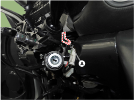
- Disconnect the multifunction switch connector (A).
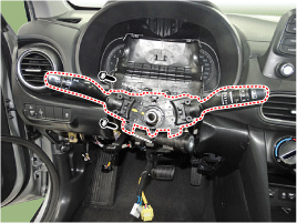
- Loosen the screws (2EA) on the multifunction switch assembly.
Installation
- Install the multifunction switch.
- Install the clock spring and steering wheel.
- Install the upper and lower steering column covers.
- Install the steering wheel.
Inspection (with Multifunction Switch)
- While pressing each switch, check the electrical continuity between the multifunction switch connector and ground. If the continuity does not meet the specification, replace the switch.
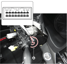
Description Switch No Resistance value (Ω, ±1%) Wiper Switch Signal FOG 1 - 9 330 OFF ∞ INT (AUTO) 470 Low 1000 High 3900 Front Wiper INT Volume Level 1 7 - 9 330 Level 2 690 Level 3 1310 Level 4 2610 Level 5 7310 Fog Light Switch OFF 9 - 10 ∞ ON 910 Turn Signal Switch OFF 9 - 12 ∞ Left 910 Right 2910 Headlamp High/Low Beam Switch OFF 9 - 13 ∞ Passing 910 Dimmer 2910 Switch OFF 9 - 14 ∞ Auto 680 Rear Lamp 1680 Headlamp (Low Beam) 5580 - Body electrical system malfunctions can be quickly diagnosed with the Global Diagnostic System (GDS). The GDS provides the following information.
- Self-Diagnosis: Diagnostic Trouble Code (DTC) check and display
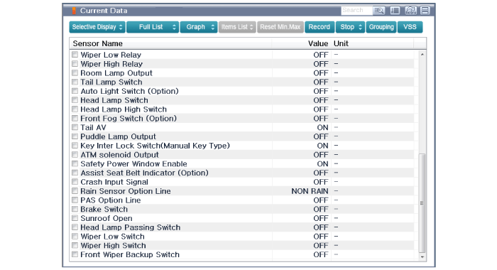
- Current Data: Check the system input/output status.
- Actuation Test: Check the system operating status
- Additional function: other control such as option system and zero point setting
- Select "Vehicle Model" and the system to be checked to inspect the vehicle with the tester.
- Select "Body Control Module (BCM)" to inspect the Body Control Module (BCM).
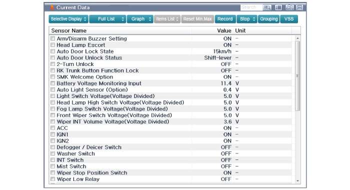
- Select the "Current Data" menu to check the current input/output status. The input/output data for the sensors connected to the Body Control Module (BCM) can be checked.
Test yourself
A quick Hyundai Kona quiz: every answer comes with an explanation and a link to the manual page.
Was this page helpful?