Engine Electrical System
GENERATOR
In this manual: Engine Electrical System
19steps
~114min
4/5difficulty
Done 0 of 19
Description and Operation
Description
The alternator consists of eight built-in diodes, which convert alternating current to direct current. Direct current is then output from terminal "B" of the alternator. In addition, the charging voltage of this alternator is controlled by the battery voltage detection system. The alternator is controlled by the battery voltage sensing system. The main components of the alternator are the rotor, stator, rectifier, capacitor brushes, bearings, and V-ribbed belt pulley. The brush holder has a built-in electronic voltage regulator.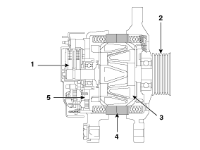
1. Brushes 2. Pulley 3. Rotor 4. Stator 5. Rectifier
Specifications
Specification
GENERATOR| Item | Specification | |
| Rated Voltage | 13.5 V, 150 A | |
| Usage Rate | 1000 ~ 18000 rpm | |
| Voltage Regulator | Built-in Regulator IC | |
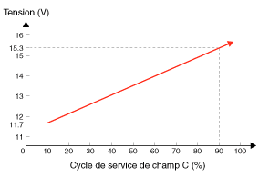
| Regulator Set Voltage | External mode | See figure below |
| Internal mode | 14.55 ± 0.3 V | |
| Temperature Coefficient | External mode | 0±3 mV/°C |
| Internal mode | -3.5±2 mV/°C | |
Components and Component Location
COMPONENTS
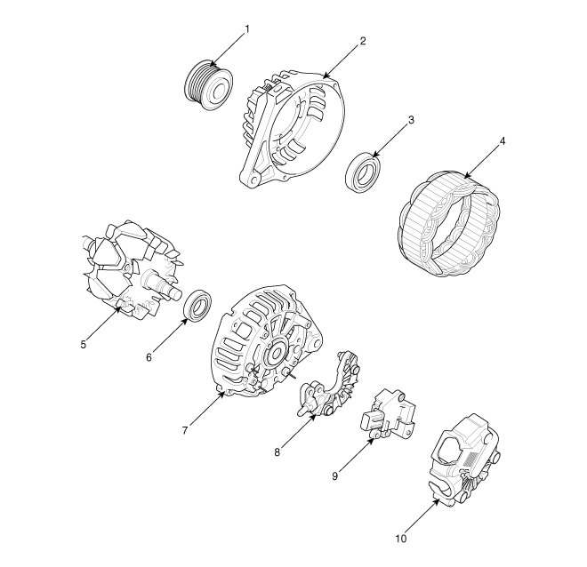
| 1. Pulley 2. Front Cover 3. Front Bearing 4. Stator 5. Rotor |
6. Rear Bearing 7. Rear Cover 8. Rectifier Assembly 9. Regulator 10. Rear Cover |
Circuit Diagrams
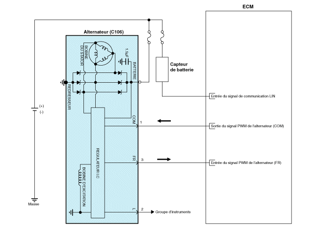
Wiring Diagram
Repair Procedures
DEPOSIT
- Disconnect the negative battery cable.
- Remove the drive belt. (Refer to Engine Mechanical System - "Drive Belt")
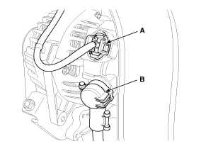
- Disconnect the alternator connector (A) and the cable (B) from the alternator "B" terminal.
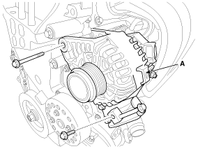
- Remove the through bolt and remove the alternator (A).
REMEDY
- To install, perform the removal procedure in reverse order.
- After installation, adjust the alternator belt tension. (Refer to Engine Mechanical System - "Drive Belt") Alternator mounting bolt: [M10] 29.4 ~ 41 N·m [M8] 21.6 ~ 32 N·m
DISASSEMBLY
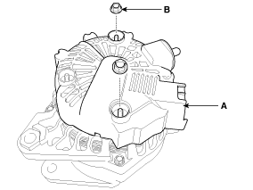
- Remove the rear cover (A) after loosening the nuts (B).
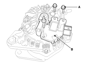
- Remove the mounting bolts (A) and the regulator assembly (B).
- Remove the slip ring guide (A) by pulling it out.
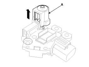
- Remove the pulley (A).
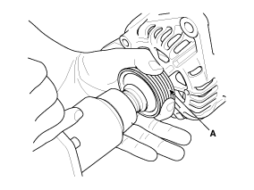
- Unsolder the 3 stator wires (A).
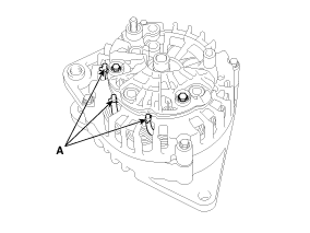
- Remove the 4 through bolts (A).
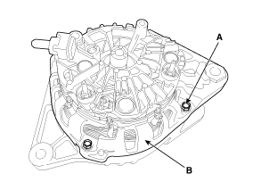
- Separate the rotor (A) and housing (B).
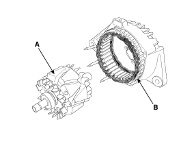
Installation
- For reassembly, perform the removal procedure in reverse order.
Inspection
[Rotor]
- Make sure the sliding ring continuity is effectively established between the rings (C).
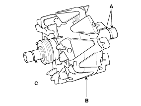
- Make sure there is no continuity between the slip rings and the rotor (B) or the rotor shaft (A).
- If either of the two rotor continuity tests is out of specification, replace the alternator.
[Stator]
- Make sure there is no continuity between each pair of cables (B).
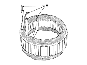
- Make sure there is no continuity between each cable and the coil core.
- If either of the two coil continuity tests is out of specification, replace the alternator.
Test yourself
A quick Hyundai Tucson quiz: every answer comes with an explanation and a link to the manual page.
Was this page helpful?