Heating, Ventilation and Air Conditioning
With Temperature Control Servo
In this manual: Heating, Ventilation and Air Conditioning
21steps
~126min
4/5difficulty
Done 0 of 21
Components and Component Location
Component location
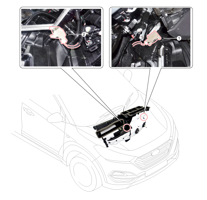
| 1. Temperature Control Actuator [G] | 2. Temperature Control Actuator [D] |
Description and Operation
Description
The temperature control actuator is located on the heater unit. It controls the temperature as follows. The signal from the control unit adjusts the position of the temperature door by activating the temperature actuator. The temperature is then controlled by the warm/cold air mix ratio set according to the position of the temperature door.Repair Procedures
Inspection
- Turn the ignition switch to the OFF position.
- Disconnect the temperature control actuator connector.
- Check that the temperature control actuator operates to the cold position when 12 V is applied to terminal 3 and ground terminal 7. Check that the temperature control actuator operates to the hot position when connected in reverse. [Driver Side Temperature Control Actuator]

1.-
2.-
3. Hot Position
4. Cold Position5. Sensor Ground
6. Feedback Signal
7. Sensor (+5V)
[Passenger Side Temperature Control Actuator]1.-
2.-
3. Cold Position
4. Hot Position5. Sensor (+5V)
6. Feedback Signal
7. Sensor Ground - Connect the temperature control actuator connector.
- Start.
- Check the voltage between terminals 5 and 6.Specification
Door Position VOLTAGE (V) Fault Detection Maximum Cooling 0,4±0,15 Low voltage: 0.1 V or less
High voltage: 4.9 V or moreMaximum Heating 4,6 ± 0,15 - If the measured voltage does not meet the specification, check operation by replacing the existing temperature control actuator with a new genuine part. Then determine whether replacement of the temperature control actuator is required.
Diagnosis with GDS
- The heating, ventilation and air conditioning (HVAC) system can be diagnosed quickly (defective parts) using the Global Diagnostic System (GDS). ※ The GDS provides the following information. (1) Self-diagnosis: checks and displays diagnostic trouble codes (DTC). (2) Current data: checks the status of input/output signals. (3) Active test: checks system operating conditions. (4) Additional functions: in addition to control, such as zero point adjustment.
- Select the "Vehicle Model" and the system to be checked in order to inspect the vehicle with the scan tool.
- Select the "Current Data" menu to check the current status of the input/output data. The input/output data for the sensors corresponding to the temperature control actuator can be checked.

- To perform a forced operation on the inputs of the temperature control actuator, select "ACTUATOR TEST" in the temperature control menu.
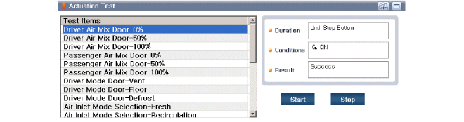
REPLACEMENT
(Driver Side)- Disconnect the negative (-) battery terminal.
- Remove the lower airbag panel. (Refer to Body - "Lower Instrument Panel")
- Remove the driver side spray hose (A) after loosening the clamp.
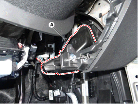
- Disconnect the connector (A), then remove the driver side temperature control actuator (B) after loosening the mounting screws.

- To install, perform the removal procedure in reverse order.
- Disconnect the negative (-) battery terminal.
- Remove the center instrument panel. (Refer to Body - "Center Instrument Panel")
- Remove the passenger side spray hose (A).
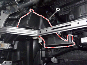
- Disconnect the connector (A), then remove the passenger side temperature control actuator (B) after loosening the mounting screws.

- To install, perform the removal procedure in reverse order.
Test yourself
A quick Hyundai Tucson quiz: every answer comes with an explanation and a link to the manual page.
Was this page helpful?