Steering System
Repair Procedures
In this manual: Steering System
7steps
~42min
2/5difficulty
Done 0 of 7
GENERAL INSPECTION
Diagnostic Note
| Failure rate | Inspection item | Symptom | EXPLANATION | Noticed |
| Drop, Impact and Overload | Engine |
|
|
|
| ECU |
|
|||
| TORQUE SENSOR |
|
|
|
|
| WOOD |
|
|
||
| pull / push | Beam |
|
|
|
| Abnormal storage temperature | Engine / ECU |
|
|
|
- Do not strike electronic parts; if dropped or struck, replace them.
- Avoid heat and mold on electronic parts.
- Do not touch the connection terminal to avoid deformation and static electric shock.
- Do not strike the engine and torque sensor parts; if dropped or struck, replace them.
- Connectors must be disconnected or connected with the ignition in the ALL OFF position.
MDPS System Inspection and Diagnosis
Before or after servicing the EPS system, perform the troubleshooting procedure and check as follows. Compare the system condition with the normal condition in the table below, and if an abnormal symptom is found, apply the necessary tool and perform the inspection.| TEST CONDITIONS | Symptoms | Passenger Duration |
Warning Light | Cause | Inspection Item | |
| IGN OFF / Engine OFF / Stationary | Steering malfunction | - | - | - | Normal | |
| Power steering assist operation | 120 seconds | Indicator is illuminated. | Full power is applied even when ALL is off. Steering angle direction is not initialized. |
|
||
| 120 seconds | The indicator is off. | Cluster or CAN signal malfunction | Operate the cluster, cluster line and communication line MAY. | |||
| ALL ON / Engine OFF / Stationary | - | Steering malfunction | - | - | - | Normal |
| Power steering assist operation | 120 seconds | Indicator is illuminated. | Steering angle is not initialized. | Use a scan tool to initialize the steering wheel angle. | ||
| 120 seconds | The indicator is off. | Cluster or CAN signal malfunction | Operate the cluster, cluster line and communication line MAY. | |||
| When the engine is running, ALL remains on but the engine stops. | 120 seconds | Indicator is illuminated. | No EMS signals received (CAN communication) | Check the communication line. MAY. | ||
| 120 seconds | The indicator is off. | Cluster or CAN signal malfunction | Operate the cluster, cluster line and communication line MAY. | |||
| ALL ON / Engine running / Stationary | Steering malfunction | - | Indicator is illuminated. | Power supply line faults in EPS and ALL system | Check the EPS and ALL system power supply lines. | |
| - | Indicator is illuminated. | Diagnostic Trouble Code (DTC) is displayed | Use a scan tool to diagnose and troubleshoot. | |||
| Power steering assist operation | - | - | - | Normal | ||
| - | Indicator is illuminated. | Diagnostic Trouble Code (DTC) is displayed | Use a scan tool to diagnose and troubleshoot. | |||
ASP: Absolute Steering Position CAN network controller + Area EMS: Engine Management System
DBDM System Maintenance Schedule
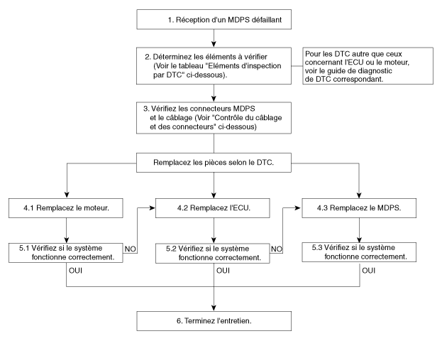
DTC Inspection Items
| diagnostic trouble codes | Cause | Symptoms | Inspection Item |
| C1112 | Sensor Supply Voltage | ① MDPS LED is on ② Steering malfunction |
|
| C1604 | ECU hardware error | ||
| C1704 | ECU safety relay malfunction | ||
| C2401 | Motor position sensor error |
|
|
| C2412 | Motor circuit short to ground or open circuit | ||
| C2413 | Motor current error |
Connector and Wiring Inspection
- Connector and Wiring Inspection. Check connectors and wiring for damage, pushed back pins, or poor connection.
- Check the vehicle side wiring.
- Make sure there is no short to ground or open circuit caused by poor connection, damage, or foreign material.
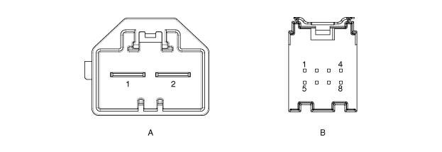
Connector Name PIN Function MDPS_Power (A) 1 Battery (+) 2 Battery (-) MDPS_Unit (B) 1 Ignition 2 - 3 - 4 - 5 - 6 - 7 CAN High 8 CAN Low - Check the wiring on the ECU side (three-phase motor).
- Make sure there is no short to ground or open circuit caused by poor connection, damage, or foreign material.

PIN Pin name 1 Could 2 PV 3 approx. - Check the motor connector.
- Terminal expansion and damage.
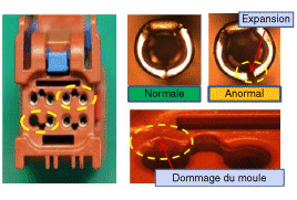
- Check the motor wiring.

- Check the vehicle side wiring.
Test yourself
A quick Hyundai Tucson quiz: every answer comes with an explanation and a link to the manual page.
Was this page helpful?