Braking System
Troubleshooting
In this manual: Braking System
92steps
~552min
5/5difficulty
Done 0 of 92
TROUBLESHOOTING
- ESP and TCS control is strictly prohibited in case of ABS malfunction.
- If the ESP or TCS malfunctions, only the faulty system is prohibited.
- However, if you want to disable the solenoid valve in case of ESP malfunction, refer to the integrated ABS safety system.
- The information on the integrated ABS safety system is identical to the integrated safety system without ESP installed.
- The code is stored in memory as long as the power supply to the indicator remains connected. (O)
- The code is stored in memory as long as the HCU remains powered. (X)
- The initial evaluation is performed immediately after the HECU unit is connected.
- The valve relay evaluation is performed immediately after ALL2 ON.
- The report continues to run as long as ALL2 is on.
- Turn off the system, perform the following actions and wait until HECU power is disconnected.
- Turn off the valve relay.
- Stop control during operation and do not perform any actions until normal conditions are found.
- The ESC warning lamp illuminates for 3 seconds after ignition ON.
- The ESC function lamp flashes when ESC is activated.
- If ESC is not operating, the ESC warning lamp illuminates.
- The ESC OFF lamp illuminates when
- ESC switch
- 3 seconds after ignition ON.
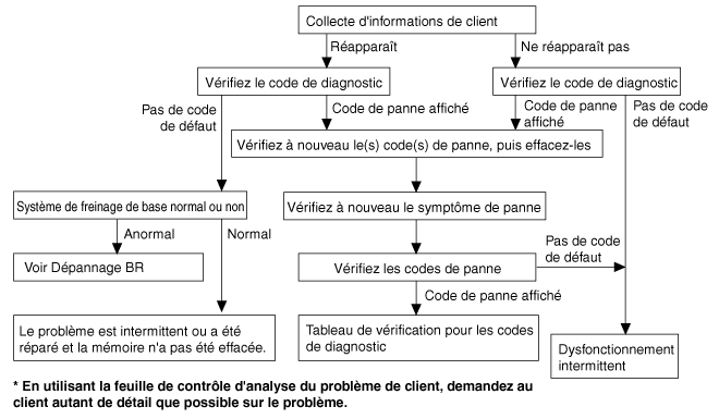
| Condition | EXPLANATION |
| System Check Audible Warning | When the engine is started, a loud noise may sometimes be heard from inside the engine compartment. This is caused by the system self-check operation being completed. |
| ABS Operation Noise |
|
| ABS Operation (Longer Stopping Distance) | On snow-covered or gravel roads, the braking distance of a vehicle equipped with ABS may sometimes be longer than for other vehicles. Accordingly, advise the customer to drive carefully and reduce vehicle speed on such surfaces. |
| Diagnostic conditions may vary depending on the trouble code. If the DTC was erased, make sure the conditions meet the requirements specified in the "Comments". |
|
ABS Order Form
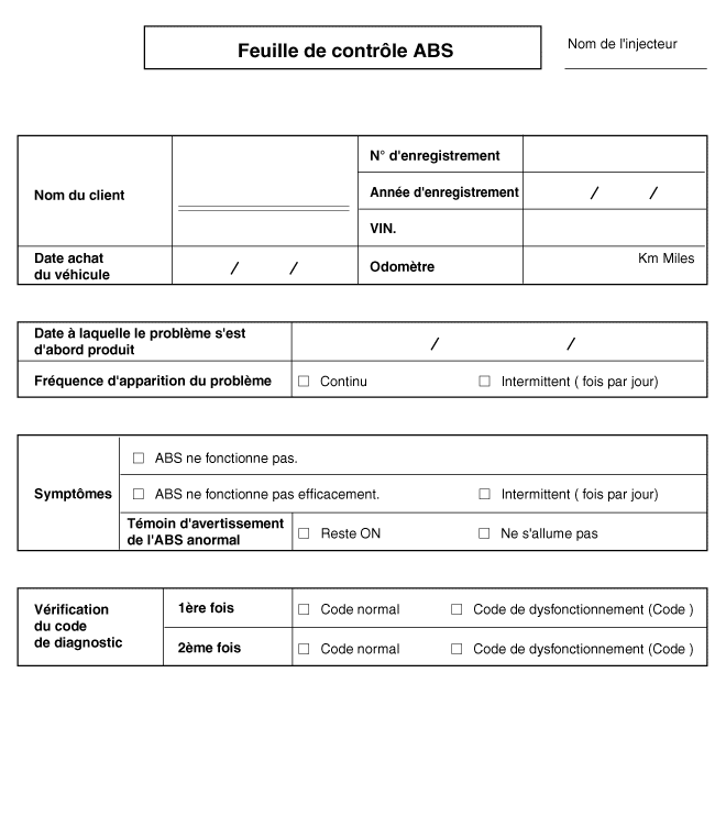
| Symptom | Suspected Area |
| ABS does not operate. | Only if items 1~4 are all normal and the problem still persists, replace the HECU.
|
| ABS operates intermittently. | Only if items 1~4 are all normal and the problem still persists, replace the ABS hydraulic unit/pump assembly.
|
| Communication with GDS is not possible. (Communication with any system is not possible) |
|
| Communication with GDS is not possible. (Communication with ABS only is not possible) |
|
| When the ignition switch is turned ON (engine OFF), the ABS warning lamp does not illuminate |
|
| Even after starting the engine, the ABS warning lamp remains illuminated |
|

| Symptom Inspection | Possible Cause |
| Brake operation depends on driving conditions and road surface condition, so diagnosis may be difficult. However, if a normal trouble code is displayed, check the following possible cause. If the problem is not resolved, replace the ESC control module. |
|
INSPECTION PROCEDURES: CHECK WHEEL SPEED SENSOR
- Connect the GDS to the diagnostic connector and turn the ignition switch ON.
- Make sure that a DTC is output.
- Is a DTC output?

▶ Check the power supply circuit. 
▶ Erase the trouble code and check again using the GDS. - Disconnect the connector from the ESC control module.
- Turn the ignition ON, measure the voltage between terminal 29 of the connector on the ESC control module harness side and ground.
Specification: Approximately B+
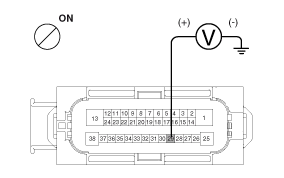
- Is the voltage within specification?
▶ Check the ground circuit. ▶ Check the harness or connector between the fuse (10A) in the engine compartment junction block and the ESC control module. Repair if necessary. - Disconnect the connector from the ESC control module.
- Check the continuity of the circuit between terminals 13, 38 of the connector on the ESC control module harness side and the ground point.
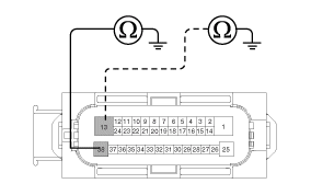
- Is there continuity?
▶ Check the wheel speed sensor circuit. ▶ Repair the open circuit in the wiring and the ground points. - Refer to DTC troubleshooting procedures.
- Is this normal?
▶ Make sure the hydraulic circuit has no leakage. ▶ Repair or replace the wheel speed sensor. - Refer to hydraulic lines.
- Check for leakage in the hydraulic lines.
- Is this normal?
▶ If the problem persists, replace the ESC control module. ▶ Eliminate leakage from the hydraulic lines. 
| Symptom Inspection | Possible Cause |
| Brake operation depends on driving conditions and road surface condition, so diagnosis may be difficult. However, if a normal trouble code is displayed, check the following possible cause. If the problem is not resolved, replace the ESC control module. |
|
INSPECTION PROCEDURES: CHECK WHEEL SPEED SENSOR
- Connect the GDS to the diagnostic connector and turn the ignition switch ON.
- Make sure that a DTC is output.
- Is a DTC output?
▶ Check the wheel speed sensor circuit. ▶ Erase the trouble code and check again using the GDS. - Refer to DTC troubleshooting procedures.
- Is this normal?
▶ Check the stop lamp switch circuit. ▶ Repair or replace the wheel speed sensor. - Make sure the stop lamp illuminates when the brake pedal is depressed and goes off when the brake pedal is released.
- Measure the voltage between terminal 23 of the connector on the ESC control module harness side and body ground while the brake pedal is depressed.
Specification: Approximately B+
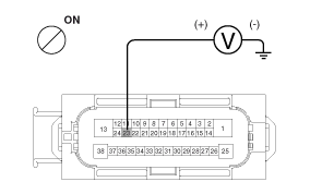
- Is the voltage within specification?
▶ Make sure the hydraulic circuit has no leakage. ▶ Repair the stop lamp switch. Repair any open circuit in the wiring between the ESC control module and the stop lamp switch. - Refer to hydraulic lines.
- Check for leakage in the hydraulic lines.
- Is this normal?
▶ If the problem persists, replace the ESC control module. ▶ Eliminate leakage from the hydraulic lines. 
| Symptom Inspection | Possible Cause |
| Probable failure of the power supply (including ground) of the diagnostic line. |
|
INSPECTION PROCEDURES: CHECK DIAGNOSTIC POWER SUPPLY CIRCUIT
- Measure the voltage between terminal 16 of the data link connector and body ground.
Specification: Approximately B+
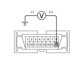
- Is the voltage within specification?
▶ Check the diagnostic ground circuit. ▶ Repair the open circuit in the wiring. Check and replace the fuse and junction block in the engine compartment. - Check the continuity between terminal 4 of the data link connector and body ground.
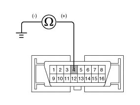
- Is there continuity?
▶ Repair the open circuit in the wiring between terminal 4 of the data link connector and the ground point. 
| Symptom Inspection | Possible Cause |
| If communication with GDS is not possible, the cause may be an open in the HECU power supply circuit or an open in the diagnostic output circuit. |
|
INSPECTION PROCEDURES: Check the CAN line for continuity.
- Disconnect the connector from the ESC control module.
- Check the continuity of the circuit between terminals 26, 14 of the control panel module connector and terminals 3, 11 of the data link connector.
- Is there continuity?
▶ Check the power supply to the ESC control module. ▶ Repair the open circuit in the wiring. - Disconnect the connector from the ESC control module.
- Turn the ignition ON, measure the voltage between terminal 29 of the connector on the ESC control module harness side and ground.
Specification: Approximately B+
- Is the voltage within specification?
▶ Make sure the ground is not faulty. ▶ Check the wiring harness, cable or connector between the fuse (10A) in the engine compartment junction block and the ESC control module. Repair if necessary. - Check the continuity between terminal 4 of the data link connector and the ground point.
▶ Replace the ESC control module and recheck. ▶ Repair the open circuit in the wiring or the faulty ground.

| Symptom Inspection | Possible Cause |
| When power is supplied to the HECU, the ABS warning lamp illuminates for the initial check. Therefore, if the lamp does not illuminate, the cause may be an open in the warning lamp power supply circuit, a burned-out bulb, an open in the two circuits between the ABS warning lamp and the HECU, or a faulty HECU |
|
INSPECTION PROCEDURES: CONFIRM THE CONCERN
- Disconnect the ESC control module connector and turn the ignition switch to ON.
- Does the ABS warning lamp illuminate?
▶ Recheck after replacing the ESC HECU. ▶ Check the power supply of the ABS warning lamp. - Disconnect the instrument cluster connector (M08) and turn the ignition switch ON.
- Measure the voltage between terminal 39 of the instrument cluster (M08) harness-side connector and body ground.
Specification: Approximately B+
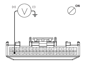
- Is the voltage within specification?
▶ Check the resistance of the ABS warning lamp CAN circuit. ▶ Check the fuse. - Disconnect the instrument cluster connector (M08) and turn the ignition switch OFF.
- Measure the resistance between terminals 32 and 33 of the instrument cluster (M08) harness-side connector.
Specification: 60 Ω
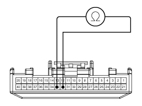
- Is the resistance within specification?
▶ Secure the ABS warning lamp bulb or the entire instrument cluster. ▶ Check the ABS warning lamp CAN wiring circuit. - Disconnect the instrument cluster connector (M08) and the ESC HECU connector, then turn the ignition switch OFF.
- Check the continuity of the circuit between terminal 32 of connector (M08) on the instrument cluster harness side and terminal 26 on the ESC HECU harness side. Check the continuity of the circuit between terminal 33 of connector (M08) on the instrument cluster harness side and terminal 14 on the ESC HECU harness side.
Specification: Less than 1 ohm
- Is the resistance within specification?
▶ Repair the short circuit between terminals 26, 14 of the ESC HECU harness connector and the ABS warning lamp module. ▶ Repair the short circuit between terminals 26, 14 of the ESC HECU harness connector and the ABS warning lamp module. 
| Symptom Inspection | Possible Cause |
| If the HECU detects a problem, it turns on the ABS warning lamp, which prevents the ABS from operating at the same time. At this point, the HECU stores the trouble code in memory. Although the normal code is output, the ABS warning lamp remains illuminated. The cause may be an open or short circuit in the ABS warning lamp circuit. |
|
INSPECTION PROCEDURES: CHECK DTC OUTPUT
- Connect the GDS to the 16-pin data link connector located behind the instrument panel cover on the driver's side.
- Check the DTC output using the GDS.
- Is a DTC output?
▶ Perform the DTC troubleshooting procedure. (Refer to Troubleshooting - DTC) ▶ Check the resistance of the ABS warning lamp CAN circuit. - Disconnect the instrument cluster connector (M08) and turn the ignition switch OFF.
- Measure the resistance between terminals 32 and 33 of the instrument cluster (M08) harness-side connector.
Specification: 60 Ω
- Is the resistance within specification?
▶ Repair the ABS warning lamp bulb or the entire instrument cluster. ▶ Check the wiring of the ABS warning lamp CAN circuit. - Disconnect the instrument cluster connector (M08) and the ESC HECU connector, then turn the ignition switch OFF.
- Check the continuity of the circuit between terminal 32 of connector (M08) on the instrument cluster harness side and terminal 26 on the ESC HECU harness side. Check the continuity of the circuit between terminal 33 of connector (M08) on the instrument cluster harness side and terminal 14 on the ESC HECU harness side.
Specification: Less than 1 ohm
- Is the resistance within specification?
▶ Repair the short circuit between terminals 26, 14 of the ESC HECU harness connector and the ABS warning lamp module. ▶ Repair the short circuit between terminals 26, 14 of the ESC HECU harness connector and the ABS warning lamp module.
Test yourself
A quick Hyundai Tucson quiz: every answer comes with an explanation and a link to the manual page.
Was this page helpful?