Steering
Repair Procedures
In this manual: Steering
14steps
~84min
3/5difficulty
Done 0 of 14
General Inspection
After or before servicing the EPS system, perform the following troubleshooting and inspection procedure. Compare the system condition with the normal condition in the table below. If an abnormal symptom is found, perform the necessary measures and inspection.| Test Conditions | Normal condition: The motor should not provide steering assist. | |
| Symptom | Possible Cause | Remedy |
| Ignition OFF | The motor provides steering assist. | ASP is not calibrated. | Perform ASP calibration using the scan tool. |
| IG Power Supply Circuits | Inspect the IG power supply line. | |
| Test Conditions | Normal condition: The motor should not provide steering assist, and the warning lamp should illuminate. | |
| Symptom | Possible Cause | Remedy |
| IG ON / Engine OFF | The motor provides steering assist. | ASP is not calibrated. | Perform ASP calibration using the scan tool. |
| EMS CAN signal not received. | Inspect the CAN line. | |
| The warning lamp does not illuminate. | Cluster Malfunction | Inspect the cluster and cluster harness. |
| Test Conditions | Normal condition: The motor provides steering assist, and the warning lamp does not illuminate. | |
| Symptom | Possible Cause | Remedy |
| IG ON / Engine ON | The warning lamp illuminates, and the motor does not provide steering assist. | EPS (Battery Power) and IG Power Supply Malfunction | Inspect the connector and harness for EPS (Battery Power) and the IG power supply line. |
| DTC is detected by the system. | Perform a self-diagnosis using a scan tool, and repair or replace as necessary. | |
| The warning lamp illuminates, and the motor provides steering assist. | ASP is not calibrated. | Perform ASP calibration using the scan tool. |
| CAN communication error between EPS and cluster. | Inspect the CAN line. | |
ASP: Absolute Steering Position, CAN: Controller Area Network, EMS: Engine Management System
|

MDPS Diagnosis Principle
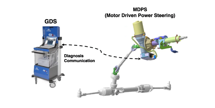
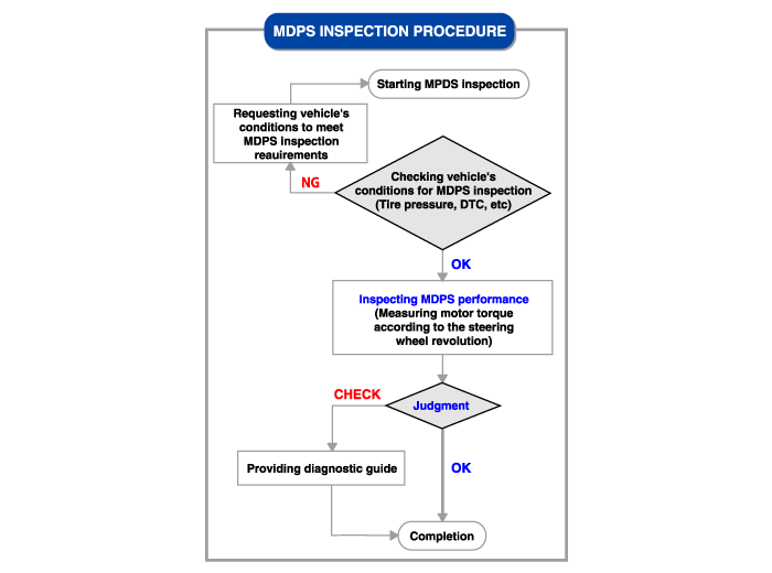
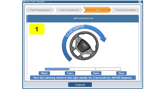
This bulletin provides the diagnostic procedure for the Motor-Driven Power Steering (MDPS) system using GDS to diagnose heavy steering effort, abnormal steering component position, and the MIL indicator in the steering system.- GDS evaluates the normal/abnormal condition of the MDPS by calculating the MDPS motor torque generated when the steering wheel is turned left and right 360° in 3 seconds.
- Connect the Data Link Connector (DLC) (16-pin), located under the driver's side crash pad lower panel, to the scan tool.
- Turn on the scan tool after turning the ignition switch ON.
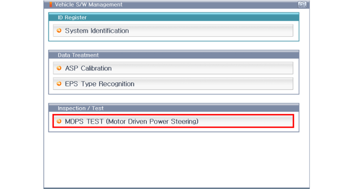
- After selecting "Vehicle Model" and "System," select "MDPS TEST" on the GDS vehicle selection screen.
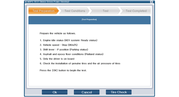
- Prepare the vehicle according to the required vehicle conditions.
- Check for MDPS-related DTCs, and then clear them if any are found.
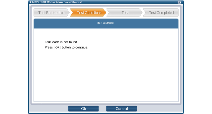
- Perform the MDPS TEST.
- If the MDPS function check result is "OK," press "OK" and complete the service procedure.
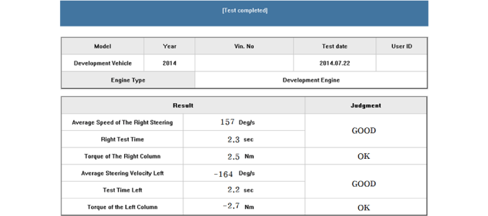
- If the MDPS check result is "Check," press "Check," and then inspect the items listed below.
- EPS Warning Lamp Illuminated
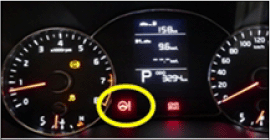
A. Check the DTCs related to the steering system. Trouble Code Type Service Action C1112 EPS Warning Lamp Illuminated Perform repairs in accordance with the DTC troubleshooting procedure. C1290 C1604 C1704 C1705 C2400 C2401 C2412 C2413 - Vibration and Noise
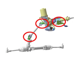
A. Inspect the MDPS components that are attached to the housing. (Check the tightening condition of the bolts and nuts.) B. Inspect the universal joint mounting bolts. - Check for excessive steering wheel effort
A. Check the tire pressure and width. B. Check whether excessive steering effort occurs when vehicle speed is not detected. C. Check the DTC codes related to the CAN communication error. Trouble Code Type Service Action C1611 CAN Communication-Related DTCs Perform diagnosis if the DTCs do not recur after the DTCs are cleared. C1616 C1622 C1692 C1628 C1693 Check the CAN line if the DTCs recur after the DTCs are cleared. C1614 C1696 C1697 C1812 C1817 - Other DTC Solutions
Trouble Code Type Service Action C1102 Low Battery Voltage Perform diagnosis after inspecting the battery. C1109 C1261 Steering Wheel Angle Zero Point Setting Reset the Steering Wheel Angle to the Zero Point C1603 Overheated Perform the test again after the MDPS motor has cooled down.
- EPS Warning Lamp Illuminated
|
- Connect the Data Link Connector (DLC) (16-pin), located under the driver's side crash pad lower panel, to the scan tool.
- Turn on the scan tool after turning the ignition switch ON.
- After selecting "Vehicle Model" and "System", select "ASP Calibration" on the GDS vehicle selection screen.
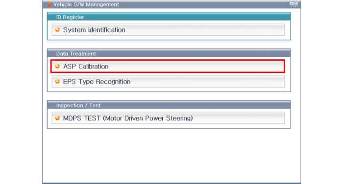
- Connect the Data Link Connector (DLC) (16-pin), located under the driver's side crash pad lower panel, to the scan tool.
- Turn on the scan tool after turning the ignition switch ON.
- After selecting "Vehicle Model" and "System", select "EPS Type Recognition" on the GDS vehicle selection screen.
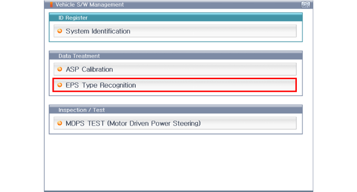
Test yourself
A quick Hyundai Tucson LM quiz: every answer comes with an explanation and a link to the manual page.
Was this page helpful?