Fuel System (DFI)
Fuel Injector Output Voltage Inspection
In this manual: Fuel System (DFI)
~3min read
NOTE
Be sure the battery is fully charged.
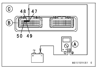
- Turn the ignition switch to OFF.
- Remove the ECU (see ECU Removal).
Do not disconnect the ECU connector
- Connect a digital meter [A] to the connector (gray) [B] with the needle adapter set.
Special Tool - Needle Adapter Set: 57001-1457
Primary Fuel Injector Output Voltage [C] Connections to ECU Connector:
For Primary Fuel Injector #1
Digital Meter (+) → BL/R lead (ECU terminal 47)
Digital Meter (–) → Battery (–) terminal
For Primary Fuel Injector #2
Digital Meter (+) → BL/O lead (ECU terminal 48)
Digital Meter (–) → Battery (–) terminal
For Primary Fuel Injector #3
Digital Meter (+) → BL/BK lead (ECU terminal 49)
Digital Meter (–) → Battery (–) terminal
For Primary Fuel Injector #4
Digital Meter (+) → BL/Y lead (ECU terminal 50)
Digital Meter (–) → Battery (–) terminal
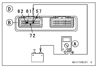
Secondary Fuel Injector Output Voltage [D]
Connections to ECU Connector: For Secondary Fuel Injector #1
Digital Meter (+) → O/R lead (ECU terminal 57)
Digital Meter (–) → Battery (–) terminal
For Secondary Fuel Injector #2
Digital Meter (+) → O/G lead (ECU terminal 72)
Digital Meter (–) → Battery (–) terminal
For Secondary Fuel Injector #3
Digital Meter (+) → O/BK lead (ECU terminal 61)
Digital Meter (–) → Battery (–) terminal
For Secondary Fuel Injector #4
Digital Meter (+) → O/Y lead (ECU terminal 62)
Digital Meter (–) → Battery (–) terminal
- Measure the output voltage with the engine stopped and with the connector joined.
- Turn the engine stop switch to run position.
- Turn the ignition switch to ON.
Output Voltage Standard: Battery Voltage for 3 seconds, and then 0 V
- Turn the ignition switch to OFF.
If the reading is in specification, check the ECU for its ground and power supply (see ECU Power Supply Inspection).
If the ground and power supply are good, replace the ECU (see ECU Removal/Installation).
If the reading is out of the specification, remove the ECU and check the wiring for continuity between main harness connectors.
Special Tool - Hand Tester: 57001-1394
- Disconnect the ECU and injector connector.
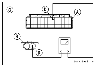
Wiring Continuity Inspection (Primary Fuel Injectors) ECU Connector (Gray) [A] ←→ Primary Fuel Injector Connector [B]
For Primary Fuel Injector #1 [C]
BL/R lead (ECU terminal 47) [D]
For Primary Fuel Injector #2
BL/O lead (ECU terminal 48)
For Primary Fuel Injector #3
BL/BK lead (ECU terminal 49)
For Primary Fuel Injector #4
BL/Y lead (ECU terminal 50)
Wiring Continuity Inspection (Secondary Fuel Injectors) ECU Connector (Gray) [A] ←→ Secondary Fuel Injector Connector [E]

For Secondary Fuel Injector #1 [F]
O/R lead (ECU terminal 57) [G]
For Secondary Fuel Injector #2
O/G lead (ECU terminal 72)
For Secondary Fuel Injector #3
O/BK lead (ECU terminal 61)
For Secondary Fuel Injector #4
O/Y lead (ECU terminal 62)
- If the wiring is good, check the ECU for its ground and power supply (see ECU Power Supply Inspection).
- If the ground and power supply are good, replace the ECU (see ECU Removal/Installation).
Test yourself
A quick Kawasaki Ninja ZX-10R quiz: every answer comes with an explanation and a link to the manual page.
Was this page helpful?