Engine Mechanical System
Engine and Transaxle Assembly Repair Procedures
In this manual: Engine Mechanical System
24steps
~144min
4/5difficulty
Done 0 of 24
Removal
|
|

- Disconnect the negative battery cable.
- Remove the engine cover.
- Remove the air cleaner assembly. (Refer to Intake and Exhaust System - "Air Cleaner")
- Remove the battery and battery tray. (Refer to Engine Electrical System - "Battery")
- Remove the engine cover. (Refer to Engine and Transaxle Assembly - Engine Room Cover)
- Drain the engine coolant. (Refer to Cooling System — Engine Coolant)
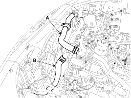
- Remove the upper radiator hose (A) and lower hose (B).
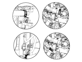
When installing the radiator hoses, install them as shown in the illustrations.
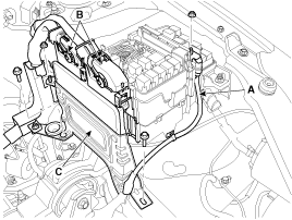
- Disconnect the (+) cable (A) from the junction box.
- Disconnect the connectors (B), then remove the ECM (C).
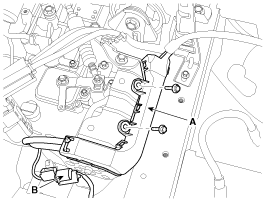
- Disconnect the front connector (B), then remove the wiring protector (A).
- Disconnect the junction box connector (A) and ground bolts (B), then remove the engine wiring from the engine compartment.
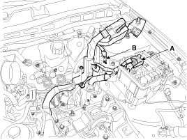
- Disconnect the transmission wiring harness connectors and the control cable from the transmission. (Refer to Automatic Transmission System - "Automatic Transmission")
- Disconnect the ATF cooler hose. (Refer to Automatic Transaxle System - "Automatic Transaxle")
- Disconnect the brake booster vacuum hose (A), PSCV hose (B) and fuel hose (C).
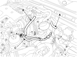
- Disconnect the heater hoses (A).
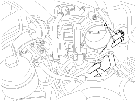
Install the heater hoses as shown in the illustrations.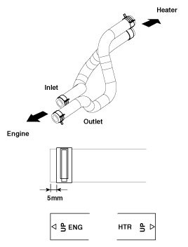
- Recover the refrigerant, then remove the high-pressure line and the low-pressure line. (Refer to Heating, Ventilation and Air Conditioning - "Compressor")
- Remove the front muffler. (Refer to Intake and Exhaust System - "Muffler")
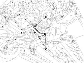
- Remove the roll rod bracket (A). Tightening torque Bolt (B): 107.9 ~ 128 N·m Bolts (C): 49.0 ~ 64 N·m
- Remove the suspension member. (Refer to Suspension System - "Suspension Member")
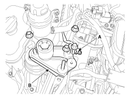
- Disconnect the ground cable (A) and remove the engine mounting bracket (B).
Tightening torque: 88.3 ~ 108 N·m
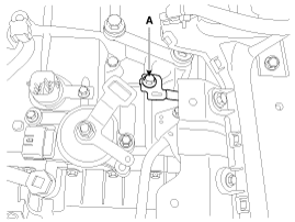
- Disconnect the transaxle ground line (A).
- Remove the service cover (A).
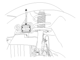
- Remove the transmission mounting bolts (A).
Tightening torque: 107.9 - 128 N·m
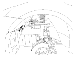
- Remove the engine and transaxle assembly by lifting the vehicle.
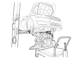
When removing the engine and transaxle assembly, be careful not to damage surrounding parts or body components.
Installation
Install in the reverse order of removal. Perform the following:- Adjust the shift cable.
- Fill the engine with engine oil.
- Fill the transmission with fluid.
- Fill the power steering fluid.
- Fill the radiator and the coolant reservoir with engine coolant.
- Set the heater control lever to the "HOT" position.
- Clean the battery terminal posts and cable clamps, then assemble.
- Inspect for fuel leaks.
- After assembling the fuel line, turn the ignition switch ON (do not operate the starter) so that the fuel pump operates for about two seconds and pressurizes the fuel line.
- Repeat this procedure two or three times, then check all fuel line connections for leaks.
- Bleed air from the cooling system.
- Start the engine and let it run until warm (until the radiator fan cycles 3 or 4 times).
- Stop the engine and let it cool down. Check the radiator coolant level and add coolant if necessary. This allows trapped air to be purged from the cooling system.
- Tightly close the radiator cap, then restart the engine and check for leaks.
Test yourself
A quick Kia Cadenza VG Owner's Manual quiz: every answer comes with an explanation and a link to the manual page.
Was this page helpful?