Body Electrical System
Hazard Lamp Switch Repair procedures
In this manual: Body Electrical System
~2min read
Inspection
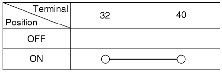
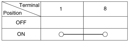
Check for continuity between terminals. If the continuity is not as specified, replace the hazard lamp switch.
[Audio Type]
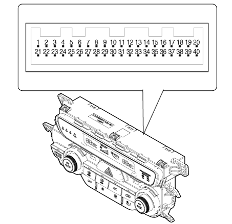
Connector Pin Information
No. Description No. Description 1 Battery (+) 21 IGN2 2 - 22 IGN1 3 Illumination (+) 23 Blower PWM 4 Sensor REF (5V) 24 Left Photo Sensor (-) 5 Driver side mode control actuator feedback 25 Right Photo Sensor (-) 6 Driver side temperature control actuator feedback 26 Blower relay 7 Intake actuator feedback 27 - 8 Evaporator temperature sensor 28 PTC relay 2 9 Ambient temperature 29 PTC relay 1 10 Driver side mode control actuator (Vent) 30 - 11 Driver side mode control actuator (Defogging) 31 Detent Out 12 Driver side temperature control actuator (Cool) 32 Hazard signal 13 Driver side temperature control actuator (Warmer) 33 P-CAN (High) 14 Intake actuator (FRE) 34 P-CAN (Low) 15 Intake actuator (REC) 35 Climate CAN (High) 16 HTD 36 Climate CAN (Low) 17 Rear defogging switch 37 Interlock (+) 18 Clean signal 38 Interlock (-) 19 Cluster Ionizer diagnosis 39 Sensor ground 20 Illumination (-) 40 Ground
[AVN Type]

No. Description No. Description 1 Ground 7 - 2 - 8 Hazard switch_output 3 - 9 - 4 Hazard switch_input 10 - 5 - 11 - 6 Battery (+) 12 -
Removal
[Audio Type]
Remove the heater & A/C control unit.
(Refer to Heating,Ventilation And Air Conditioning - "Heater & A/C Control Unit (DATC)")
[AVN Type]
Remove the AVN head unit.
(Refer to Body Electrcal System - "AVN Head Unit")
Installation
[Audio Type]
Install the heater & A/C control unit.
(Refer to Heating,Ventilation And Air Conditioning - "Heater & A/C Control Unit (DATC)")
[AVN Type]
Install the AVN head unit.
(Refer to Body Electrcal System - "AVN Head Unit")
Was this page helpful?