Heating, Ventilation, and Air Conditioning
Heater and Air Conditioning Control Unit (Dual) Repair Procedures
In this manual: Heating, Ventilation, and Air Conditioning
15steps
~90min
4/5difficulty
Done 0 of 15
Self-Diagnosis
- Self-Diagnosis Procedure
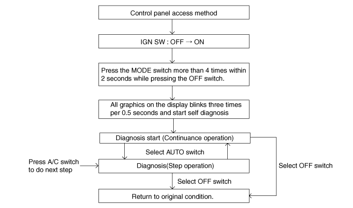
- How to read self-diagnosis code: After the display panel flashes three times every 0.5 seconds, the corresponding fault code flashes on the set temperature display panel every 0.5 seconds and shows two digits. Codes are displayed in numeric format. Fault Code
Display Description of Malfunction 00 Normal 11 In-Car Sensor Open 12 In-Car Sensor Short Circuit 13 Ambient Sensor Open 14 Ambient Air Sensor Short Circuit 17 Evaporator Sensor Open 18 Evaporator Sensor Short Circuit 19 Air Temperature Door Potentiometer Open/Short - Actuator 20 Air Temperature Door Potentiometer Malfunction - Actuator 21 Mode Door Potentiometer Open/Short 22 Mode Door Potentiometer Malfunction 23 Anti-Fog Sensor Open 24 Anti-Fog Sensor Short Circuit 25 Intake Door Potentiometer Open 26 Intake Door Potentiometer Short Circuit 32 Air Temperature Door Potentiometer Open/Short - Passenger 33 Air Temperature Door Potentiometer Malfunction - Passenger 43 Anti-Fog Door Potentiometer Open/Shorted 44 Anti-Fog Door Potentiometer Malfunction 45 APT CAN signal error 47 RPM CAN Signal Malfunction 48 Vehicle Speed CAN Signal Malfunction 49 Engine Coolant Temperature CAN Signal Malfunction 50 Cluster Ionizer Generator Malfunction 71 ECV Error (Open) - Trouble Code Display
- Continuous Operation: One DTC.

- Continuous Operation: More than two DTCs.

- STEP Operation
A. Normal code or one trouble code is the same as continuous operation. B. More than two DTCs. 
- Continuous Operation: One DTC.
- If any diagnostic trouble codes are displayed during the inspection, check the causes of the malfunction by referring to the DTC troubleshooting.
- Fail-safe
- In-Car Temperature Sensor: Check with value of 25 °C
- Ambient Temperature Sensor: Check with value of 20 °C
- Evaporator Temperature Sensor: Check with value of -2°C (28.4°F)
- Water Temperature Sensor: Monitor with value of -2°C (28.4°F) / Calculate Estimated Torque: 90 °C
- Temperature control actuator (air mix potentiometer): If the temperature setting is 17°C-24°C, 5 °C, lock in the maximum cooling position. If the temperature setting is 25°C-32°C, lock in the maximum heating position.
- Mode Control Actuator (Direction Potentiometer): Fix in the vent position when the vent mode is selected. Fix in the defrost position when any mode other than vent is selected.
- Intake Control Actuator: Fix in the fresh air position when fresh air mode is selected. Fix in the recirculation position when recirculation mode is selected.
Replacement
|

- Using a screwdriver or pry tool, remove the crash pad side cover (A).

- Loosen the mounting screws, then remove the crash pad lower panel (A).

- Disconnect the lower airbag switch connectors (A).
- Disconnect the diagnostic connector (B) and the protector under the lamp connector (C). [Left]

- Disconnect the start/stop button connector (D). [Right]

- Using a screwdriver or removal tool, remove the [RH] trim panel (A).

- After loosening the mounting screws, remove the heater control panel (A).

- Disconnect the connectors (A) and the hose (B).

- Loosen the mounting screws, then remove the heater control unit (A).

- Installation is the reverse of removal.

- Make sure the connector is properly connected.
- Replace all damaged clips.
Test yourself
A quick Kia Optima Hybrid Owner's Manual quiz: every answer comes with an explanation and a link to the manual page.
Was this page helpful?