Brake System
Description and Operation
In this manual: Brake System
7steps
~42min
2/5difficulty
Done 0 of 7
ESP Description
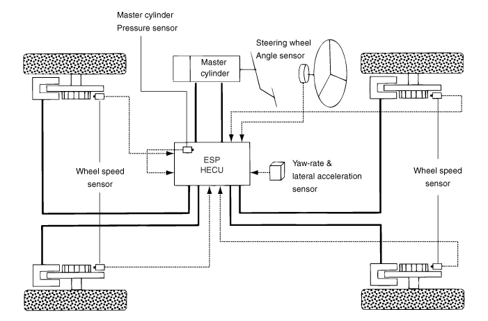
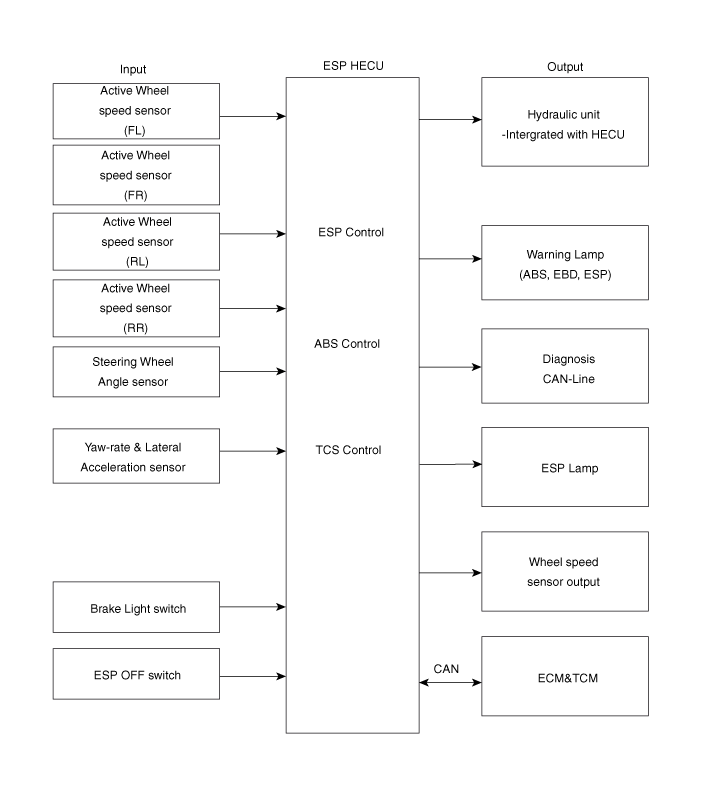
Optimal driving safety now has a name: ESP, Electronic Stability Program. ESP recognizes critical driving conditions, such as panic reactions in dangerous situations, and stabilizes the vehicle by individually braking the wheels and intervening in engine torque without the driver needing to operate the brake or accelerator pedal. ESP adds an additional function known as Active Yaw Control (AYC) to the ABS, TCS, EBD and ESP functions. While the ABS/TCS function controls wheel slip during braking and acceleration and thus mainly intervenes in the longitudinal dynamics of the vehicle, Active Yaw Control stabilizes the vehicle about its vertical axis. This is achieved by individually braking the wheels and adapting the instantaneous engine torque without any action required from the driver. ESP essentially consists of three units: sensors, electronic control unit and actuators. The stability control function operates under all driving modes and operating conditions. Under certain driving conditions, the ABS/TCS function may be activated simultaneously with the ESP function at the driver's command. In the event of a stability control function failure, the basic safety function of the ABS remains available.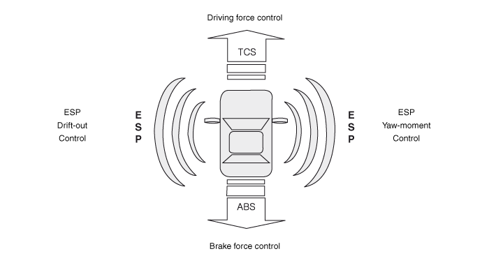
ESP Operation Mode
- STEP 1: ESP analyzes the driver's intention.

- STEP 2: It analyzes the vehicle motion with ESP.

- STEP 3: The HECU calculates the required strategy, then activates the appropriate valves and sends torque control requests via CAN to maintain vehicle stability.
- ESP not operating — normal braking.
Inlet Valve (IV) Outlet Valve (OV) Traction Control Valve (TCV) High Pressure Switching Valve (HSV) Return Pump Normal Braking Open Close Open Close OFF
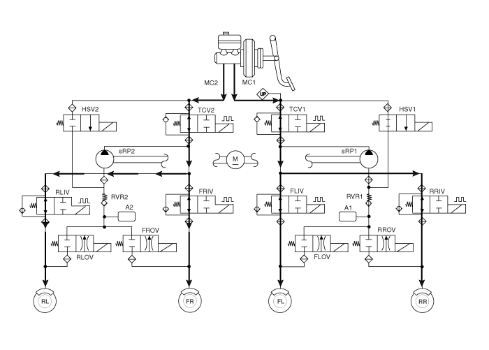
- ESP Pressure Increase Mode
Inlet Valve (IV) Outlet Valve (OV) Traction Control Valve (TCV) High Pressure Switching Valve (HSV) Return Pump Normal Braking Open Close Closed (Partially) Open ON (engine speed control)
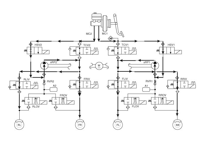
- ESP Pressure Hold Mode (controlled only for FR)
Inlet Valve (IV) Outlet Valve (OV) Traction Control Valve (TCV) High Pressure Switching Valve (HSV) Return Pump Normal Braking Close Close Closed (Partially) Open OFF
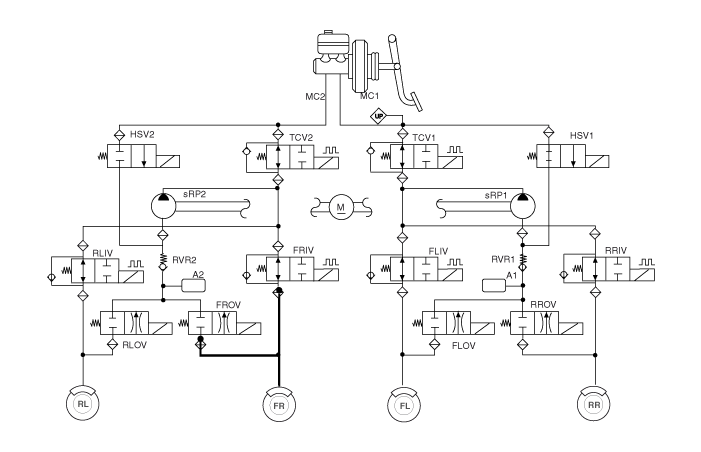
- ESP Pressure Decrease Mode (controlled only for FR)
Inlet Valve (IV) Outlet Valve (OV) Traction Control Valve (TCV) High Pressure Switching Valve (HSV) Return Pump Normal Braking Close Open Closed (Partially) Open ON (low engine speed control)
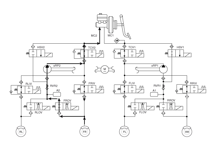
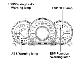
- During the initialization phase after IGN ON (continuously for 3 seconds).
- In case of ABS operation failure during braking.
- In diagnostic mode.
- When the ECU connector is disconnected from the ECU.
- During the initialization phase after IGN ON (continuously for 3 seconds).
- When the parking brake switch is on or the brake fluid level is low.
- When the EBD function has failed.
- In diagnostic mode.
- When the ECU connector is disconnected from the ECU.
- During the initialization phase after IGN ON (continuously for 3 seconds).
- When ESP function is suppressed due to a failure.
- In diagnostic mode.
- When the ESP system is operating (flashing - 2 Hz).
- During the initialization phase after IGN ON (continuously for 3 seconds).
- When the driver turns off the ESP function using the switch.
- Stage 1: The ESP engine control function stops when the ESP OFF indicator on the instrument panel illuminates by pressing the ESP OFF button for 0.15 seconds. (Brake control function operates normally.)
- Stage 2: The ESP engine and brake control functions stop when the ESP OFF indicator on the instrument panel illuminates by pressing the ESP OFF button for 3 seconds.
Test yourself
A quick Kia Cee'd quiz: every answer comes with an explanation and a link to the manual page.
Was this page helpful?