Brake System
Circuit Diagrams
In this manual: Brake System
~1min read
Schematic Diagram - ESP (1)
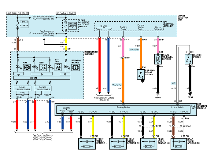
Schematic Diagram - ESP (2)
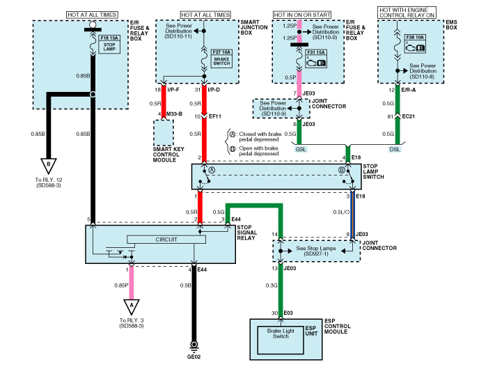
Schematic Diagram - ESP (3)
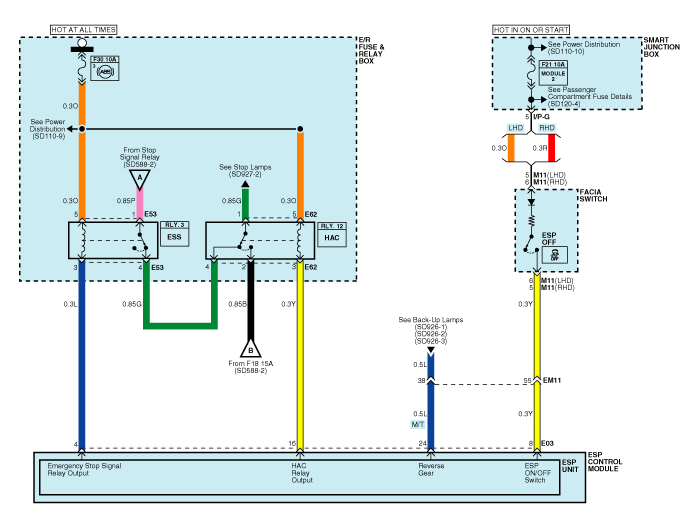
Schematic Diagram - ESP (4)
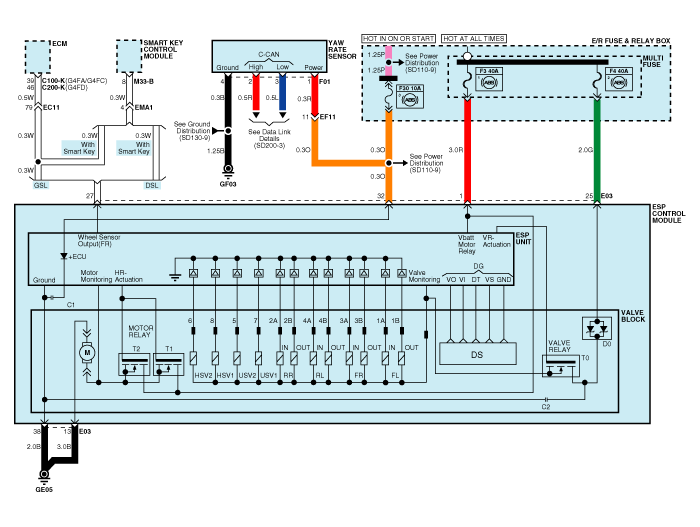
ESP Connector Input/Output

| Wire Number | Description | Current | Maximum allowable resistance of wire R_L (mOhm) | |
| Max. | min | |||
| 13 | Ground for Return Pump | 39 A | 10 A | - |
| 38 | Ground for solenoid valves and ECU |
15 A | 2 A | - |
| 1 | Power Supply for Pump Motor | 39 A | 10 A | - |
| 25 | Power Supply for Solenoid Valves | 15 A | 2 A | - |
| 32 | Voltage for hybrid ECU | 1 A | 500 mA | 60 |
| 22,6,20,31 | Wheel speed sensor signal FL, FR, RL, RR | 16.8 mA | 5.9 mA | 250 |
| 34,18,33,19 | Power supply for active wheel speed sensor FL, FR, RL, RR | 16.8 mA | 5.9 mA | 250 |
| 30 | Stop lamp switch (Signal) | 10 mA | 5 mA | 250 |
| 14 | CAN Low | 30 mA | 20 mA | 250 |
| 26 | CAN High | 30 mA | 20 mA | 250 |
| 27 | Wheel Speed Sensor Output | Open Drain | - | - |
| 8 | ESP Passive Switch (Signal) | 10 mA | 5 mA | 250 |
| 4 | ESS Output Signal | 200 mA | 100 mA | 150 |
| 16 | Brake Light Switch Input Signal | 200 mA | 100 mA | 150 |
| 10 | Parking brake switch signal | 10 mA | 5 mA | 250 |
| 23 | Clutch Switch | 10 mA | 5 mA | 250 |
Test yourself
A quick Kia Cee'd quiz: every answer comes with an explanation and a link to the manual page.
Was this page helpful?