Rear shock absorber
Components and Component Location
Components
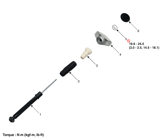
Repair Procedures
Removal
Disconnect the negative (-) battery cable.
Remove the rear wheel and tire.
(Refer to Tires/Wheels — "Wheel")
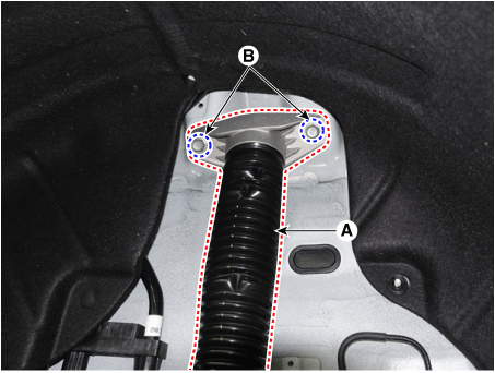
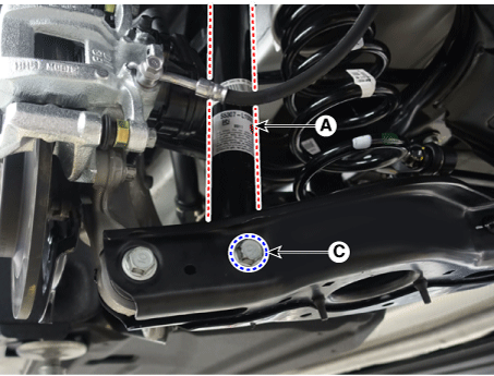
Remove the rear shock absorber (A) after loosening the bolts.
Tightening torque:
Bolt (B): 49.0 – 64 N·m
Bolt (C): 137.3 – 157 N·m lb·ft)
Installation
Install in the reverse order of removal.
Check the alignment.
(See Suspension System - Alignment)
Disassembly
Remove the lock nut cover (A).
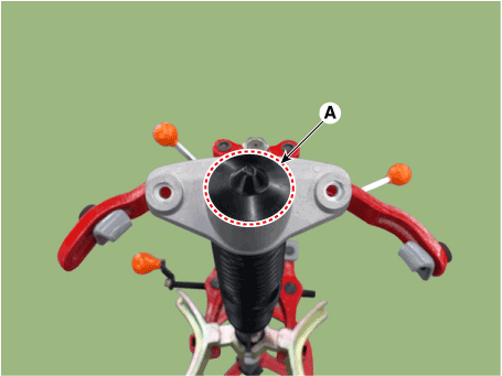
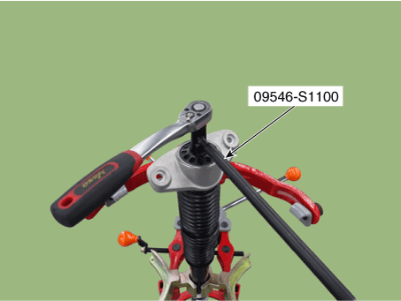
Using the special service tool (09546-S1100), install the self-locking nut.
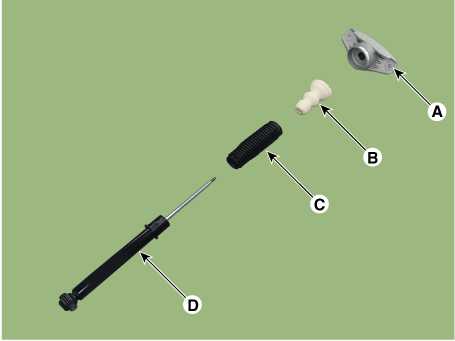
Separate the bracket assembly (A), rubber bumper (B), dust cover (C), and shock absorber (D).
Inspection
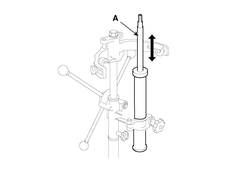
Inspect the rubber components for damage or wear.
Check the shock absorber for abnormal resistance or unusual noise.
Disposal
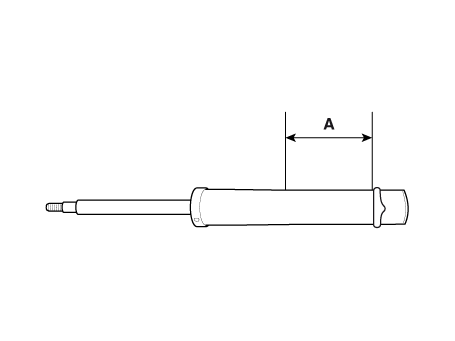
Fully extend the shock absorber piston rod.
Drill a hole to release the gas from the cylinder.
Installation
To reinstall, perform the removal procedure in reverse order.
Using SST (09546-S1100), install the lock nut.
Tightening torque: 19.6–24 N·m
Install the lock nut cover (A).
Test yourself
A quick Kia Optima DL3 quiz: every answer comes with an explanation and a link to the manual page.