Tire Pressure Monitoring System
Components and Component Location
Components
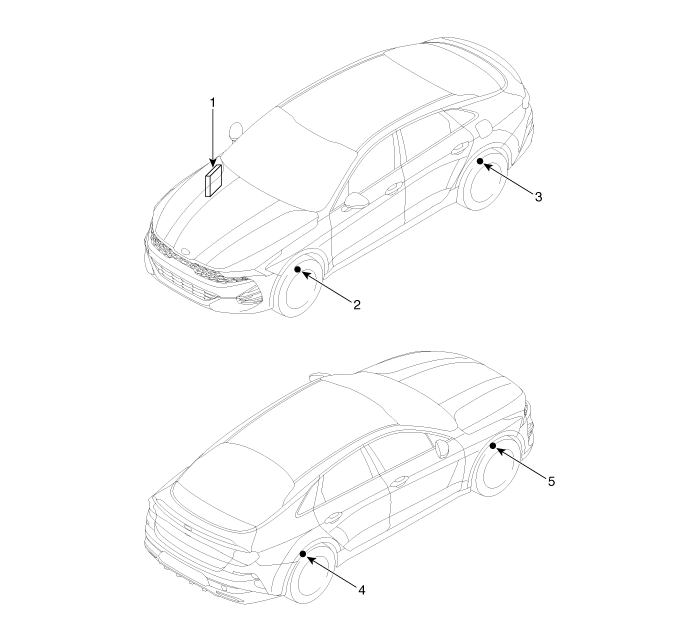
| 1. Body Control Module (BCM) 2. TPMS Sensor (FL) 3. TPMS Sensor (RL) |
4. TPMS Sensor (RR) 5. TPMS Sensor (FR) |
Description and Operation
Description
The Tire Pressure Monitoring System (TPMS) monitors the air pressure and temperature inside the tires to warn the driver of pressure changes that may affect vehicle operation. The TPMS control module analyzes information received wirelessly from the sensors. In other words, the system detects tire air pressure and warns the driver if the tire pressure drops below the specified level.
Low Tire Pressure Warning Light on Instrument Panel
Low Tire Pressure Warning Light
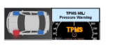
Light ON/OFF Conditions when tire pressure decreases or air leaks from the tire
Light ON
The light illuminates when the tire pressure drops below the standard level.
Light OFF
Low Tire Pressure: The warning light turns off when the tire pressure exceeds the pressure required to turn off the light.
TPMS Malfunction Indicator Lamp
Warning Conditions and Display
When the system detects a malfunction in the external operating environment (low battery voltage, abnormal vehicle speed, etc.), the warning light flashes for approximately 1 minute and then remains on.
Light OFF
The lamp turns off when the DTC is cleared. The DTC is automatically erased when the system does not receive any error signals for 30 or more ignition cycles after the previous DTC was set.
System Malfunction
General Operation
The system monitors many input elements to detect potential malfunctions.
The priority of a malfunction depends on its cause.
Some malfunctions are not diagnosed as DTCs.
The main malfunctions are as follows:
To diagnose additional malfunction symptoms when the ignition is turned on, check the warning lamp with the ignition switched on.
Check whether the warning light comes on and then turns off.
Troubleshooting
TPMS Inspection Method
Inspection
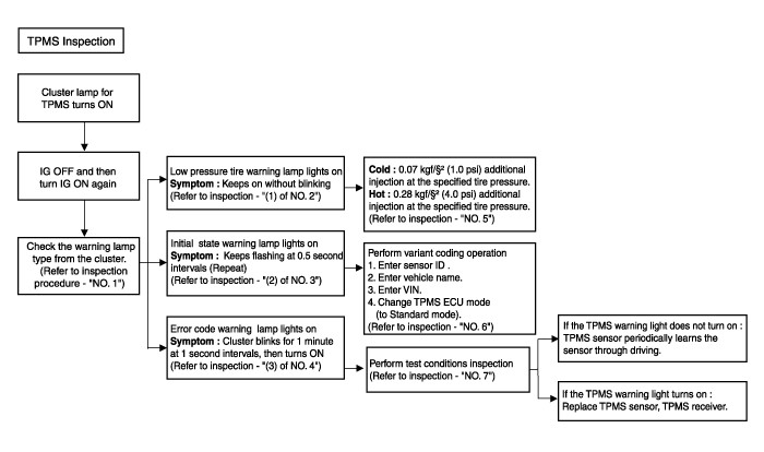
Types of Warning Lights
Steady illumination: Low tire pressure warning light
Flashes constantly at 0.5-second intervals: Initial state warning light
Flashes for 1 minute at 1-second intervals, then remains on: DTC warning light
(1) Check the condition of the warning light.
Check the condition of the vehicle warning light.
Check whether the warning light condition is caused by low tire pressure.

Symptom: Illuminates steadily.
(2) Check the condition of the warning light.
Check the condition of the vehicle warning light.
Check whether the warning light condition is caused by the initial state (initial mode) of the TPMS receiver.

(3) Check the condition of the warning light.
Check the condition of the vehicle warning light.
Check whether the warning lamp condition is caused by a malfunction code (TPMS receiver and TPMS sensor malfunction).
Symptom: The cluster flashes for 1 minute at 1-second intervals, then stays on.
Low Tire Pressure Warning Light
Cold: Vehicle has been stopped for more than 60 minutes.
→ Add 0.07 kgf/cm² (1.0 psi) above the specified tire pressure.
Hot: Vehicle
→ Add 0.28 kgf/cm² (4.0 psi) above the specified tire pressure.
Inspect the initial state warning light
A. TPMS warning lamp
(1) Check the status of the TPMS warning lamp.
(2) Flashes continuously at 0.5-second intervals. -> Initial state of the warning lamp
B. Items to check if the warning lamp is flashing
(1) Enter the sensor ID.
(Refer to TPMS Receiver - Repair Procedures)
(2) Enter the vehicle name.
(Refer to TPMS Receiver - Repair Procedures)
(3) Enter the VIN.
(Refer to TPMS Receiver - Repair Procedures)
(4) Change the TPMS ECU mode (to standard mode).
DTC checklist for performance check.
List Symptom Check Items Detailed Checklist Components C1312 (LF)
C1313 (RF)
C1314 (RL)
C1315 (RR)TPMS sensor receives an error. Sensor radio frequency transmission status Check the sensor radio frequency transmission
Check the sensor DTC
Inspect the sensor batteryTPMS sensor
Vehicle electronic unit noise
Vehicle driving conditionsC1332 (LF)
C1333 (RF)
C1334 (RL)
C1335 (RR)Sensor internal malfunction Inspect the sensor RF transmission
Sensor battery voltageCheck the sensor radio frequency transmission
Check the sensor battery (KDS)TPMS Sensor C1662 Auto learn failure Sensor RF transmission status
Check the EMS vehicle speed (VS)
Check vehicle noiseCheck the sensor RF transmission
Inspect the sensor battery
Check the EMS vehicle speed (VS)
Check vehicle electronic unit noise.TPMS sensor
Vehicle electronic unit noise
Vehicle condition
EMS vehicle speed signalC1663 Auto learn failure Sensor RF transmission status
Check the EMS vehicle speed (VS)
Check vehicle noiseCheck the sensor RF transmission
Inspect the sensor battery
Check the EMS vehicle speed (VS)
Check vehicle electronic unit noise.TPMS sensor
Vehicle electronic unit noise
Vehicle condition
EMS vehicle speed signal
Test yourself
A quick Kia Optima DL3 quiz: every answer comes with an explanation and a link to the manual page.